Yesterday, I read the whole topic again.
And I must say, since I had to study some of the schematics reading it all over again. And that made it much more clear to me.
I ordered some parts at mouser, now just have to wait till it arrives, and on with the testing.
Especially with the IV resistor, since I read this value can make a difference sound wise, in combination with the pre-amp it is connected to.
So different values I've added to the order, to test with.
(Thanks again @Supersurfer for all the input!)
Can anyone tell me how much current one D3 board and the glue logic board draws?
I know the D3 uses +5V and +26V but not sure how much current is draws. The same for the glue logic board, I know it uses +5V but not sure how much current it'll draw with one board vs two, or four.
I know the D3 uses +5V and +26V but not sure how much current is draws. The same for the glue logic board, I know it uses +5V but not sure how much current it'll draw with one board vs two, or four.
found this The D3 26V draws about 140mA, the 5V about 20mA, and the i2s2sim 5V about 5mA - 20mA (depending on how it is connected).
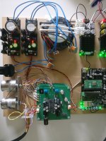
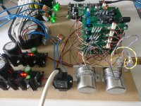
It's alive!


It turned out that the only thing in the whole project that I messed up what's the wrong IC on the i2s to continuous board.
So I replaced it, hooked everything up. And there was music.
I did learn to understand a lot more about the whole schematics, so the failure was worth it.
It sounds way better than I dared to expect when I started it.
And some tweaking can and will be done in the nearby future. After that make a nice housing!
(Something I always enjoy when the end result is achieved)
I'm interested in how much current each board id drawing so I can configure the salas regulators, What values did you see?It's alive!
View attachment 1467476View attachment 1467477
It turned out that the only thing in the whole project that I messed up what's the wrong IC on the i2s to continuous board.
So I replaced it, hooked everything up. And there was music.
I did learn to understand a lot more about the whole schematics, so the failure was worth it.
It sounds way better than I dared to expect when I started it.
And some tweaking can and will be done in the nearby future. After that make a nice housing!
(Something I always enjoy when the end result is achieved)
Oh I didn't t measure.
Just followed Ryan's lead, approx 145mA per board and some xtra.
It was a bit of tweaking before I had the load resistor right.
1.2 ohm turned out te be to high ( calculated 500mA total) couldn't get it above 25V
0.8 Ohm turned out to be workable but it became quit hot ( above 65-70 degrees C) (calculated 730mA)
So I changed it to 1 Ohm and now perfectly stable and Max 50 °C .
In the future housing it will have a nice big coolrib, so no problem I guess.(Calculated 600mA)
I used 2 salas boards, separate for left and right. This gives a bit more overhead current for the shunts without running too hot.
@Supersurfer ,👍🏼 maybe in the future,
I didn't have more ultrabib boards laying around (you did mention channel separation before to me, was that also noticeable?
I didn't have more ultrabib boards laying around (you did mention channel separation before to me, was that also noticeable?
- Home
- Group Buys
- DIY TDA1541A PCB "D3"