Hi @Ryssen,
Yes I've made the PCB, just been fine tuning the NOS boost filter. I'm quite happy with how it sounds so ill release it very soon.
Yes I've made the PCB, just been fine tuning the NOS boost filter. I'm quite happy with how it sounds so ill release it very soon.

Hi, I have a fully assembled kit with an original TDA1541A for sale. Please check the Swap Meet if interested.
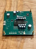
I assembled and powered up the board with a lab PS. Power on the chip (+5,-5,-15) is within few mV from expected values. The 26V consumes 130mA.
What is a requirement for the 26V and 5V PS? Is something like 1000uF after the bridge sufficient or it has to be a better quality?
Apologies if I missed this information somehow - I searched this entire thread.
What is a requirement for the 26V and 5V PS? Is something like 1000uF after the bridge sufficient or it has to be a better quality?
Apologies if I missed this information somehow - I searched this entire thread.
Attachments
Hi,
If anyone needs TDA1541, please check swap meet. I'm selling two, desoldered from CD players.
If anyone needs TDA1541, please check swap meet. I'm selling two, desoldered from CD players.
I think D3 has a regulator for every voltage. Hence my question on what is a reasonable power source to feed this board.
Hi @Seavan
For the 5V supply I use a Salas shunt, and for the 26V supply I use a capacitance multiplier.
I would suggest try a few different options and see what you like best. I didn't find much point in using something too elaborate as the on board regs do a very good job at filtering ripple.
For the 5V supply I use a Salas shunt, and for the 26V supply I use a capacitance multiplier.
I would suggest try a few different options and see what you like best. I didn't find much point in using something too elaborate as the on board regs do a very good job at filtering ripple.
Hey All,
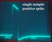
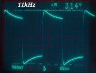
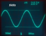
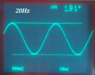
Just thought I'd share these scope shots of the tube stage im working on-
20Hz rolled off by -0.39dB from 1kHz with H2 @ -75dB and H3 @ -102.5dB
Overall the bass has been completely unaffected by the filter. Still sounds full and detailed with great control and good extension.
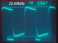
1kHz H2 @ -73.6dB and H3 @ -103.8dB
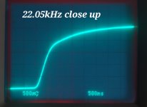
22.05kHz +3.5dB
Overall it was a balancing act to get the filter to sound smooth yet retain a fast sounding transient response.
I tried much steeper and narrower filters to suit the NOS droop more accurately but the treble became detached from the music. I found a gentle, wider slope sounded more natural even though its was technically incorrect.
From schematics here, I have changed C11 to 220nF, and changed C9 to 24.6nF, keeping the rest the same. This seems to suit my system and tastes. Others may prefer different values to suit their systems.
All fun and games! Bit more work to do though... stay tuned, ill get there in my roundabout way eventually!
Just thought I'd share these scope shots of the tube stage im working on-
20Hz rolled off by -0.39dB from 1kHz with H2 @ -75dB and H3 @ -102.5dB
Overall the bass has been completely unaffected by the filter. Still sounds full and detailed with great control and good extension.
1kHz H2 @ -73.6dB and H3 @ -103.8dB
22.05kHz +3.5dB
Overall it was a balancing act to get the filter to sound smooth yet retain a fast sounding transient response.
I tried much steeper and narrower filters to suit the NOS droop more accurately but the treble became detached from the music. I found a gentle, wider slope sounded more natural even though its was technically incorrect.
From schematics here, I have changed C11 to 220nF, and changed C9 to 24.6nF, keeping the rest the same. This seems to suit my system and tastes. Others may prefer different values to suit their systems.
All fun and games! Bit more work to do though... stay tuned, ill get there in my roundabout way eventually!
Attachments
Good work @Seavan,
Yes the socket and surrounding circuitry is set up for a 6n23p, ecc88, and a few others. Perhaps in the future ill make a different version for other tube types with different socket pinouts. What tubes would you like to use?
At the moment im thinking of changing a few things for the final version, like diode output protection, capacitor footprint pitch, and a relay to bypass the filter. Other than that im happy with the layout.
The board started up right away. Thank you for making it fun for us!
Next step is to populate the i2s-to-simultaneous board, I hear people say it sounds better. I also have a lot of records with 192k.
At this point I am planning to experiment with ECC40, but I like trying different tubes and it would be great to have that ability to replace the socket. Can I ask if you tried other tubes?
You're very welcome, its pretty fun for me too.
With this exact circuit I haven't tried any other.
I've used the ECC88 with a choke loaded anode - As per Thorsens original circuit.
Which sockets do you like?
With this exact circuit I haven't tried any other.
I've used the ECC88 with a choke loaded anode - As per Thorsens original circuit.
Do you mean the socket footprint on the PCB?ability to replace the socket.
Which sockets do you like?
I was thinking of something that would allow to use pretty much any socket, something like this:
https://www.diyaudio.com/community/attachments/grunf2-png.1322348/
https://www.diyaudio.com/community/attachments/grunf2-png.1322348/
Not a bad idea, but would require a PCB redesign, might consider this if there was enough interest for a separate pcb.
The ECC40 will not work with the on board CCS as they only go down to 8mA IIRC.
The ECC40 will not work with the on board CCS as they only go down to 8mA IIRC.
How about a DIP socket pad in the middle for a subminiature tube (wire leads)? 6021, 6111 or 6N16b?
Yes it is. Full design change is out for me, im trying to wrap things up.The 6111 is close. Maybe two submin tubes with each twin triode paralleled?
- Home
- Group Buys
- DIY TDA1541A PCB "D3"