Just finished populating this tube IV stage i've been working on for the past year.
Nice Job.
But as you have a second tube half, how about doing a Sallen Key filter around the follower? It can be made peaking to EQ the SINC roll-off. It makes it easier to construct as using inductors often get's complaints. Add a relay to switch this on-off and it can be tied into sample rate indication.
For TDA1541 27...33R I/U conversion is ok without offset current compensation (see 1541 meta thread) so we get better SNR.
Also, how about an alternative tube pinout version for 6N3/5670/2C51, which are still around NOS at sensible prices.
Thor
Thanks Thor,
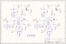
Actually the second half of the tube is used as a cathode follower, ill attach the schematic. Both channels are included on the schematic with two triodes in each tube symbol.
In the past i've tried disconnecting the 2ma current injection but wasn't sure i could notice the difference, ill try again with this tube stage.
Yeah I'd consider making an alternative pin out version if there was enough interest.
Attachments
Actually the second half of the tube is used as a cathode follower
Yes, I know. Use it as Sallen Key RC filter, which can be "peaking" to compensate the SINC roll-off instead of the RLC element in series with the I/U conversion resistor.
Example:
Riu = 33R
Ciu = 33n
SKF
R = 5k + 5k
C1 = 680p
C2 = 270p
C1' ( to create SINC EQ) 3.3nF
http://sim.okawa-denshi.jp/en/Sallenkey3Lowkeisan.htm
Thor

Ryan,Thanks chromenuts, I think you might like it. I prefer it over the single ended transformer stage I implemented.
I’m glad you’ve done this so that people can hear a tube I/V (+ buffer)and roll the sound they like. This paired with a relay attenuator with remote (mounted in the dac chassis) could be a perfect dac to amp combo with 1.8v P-P. It is certainly just enough swing for my amp pairings.
I'll have a play around with this in ltspice.But as you have a second tube half, how about doing a Sallen Key filter around the follower? It can be made peaking to EQ the SINC roll-off. It makes it easier to construct as using inductors often get's complaints. Add a relay to switch this on-off and it can be tied into sample rate indication.
Tried this a few days ago, it sounds cleaner, but different at the same time. I think ill keep it this way. (Removed R32, R33 from D3 PCB)For TDA1541 27...33R I/U conversion is ok without offset current compensation (see 1541 meta thread) so we get better SNR.
Thanks for your advice. 🙂
Hi All,
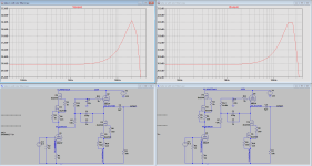
I tried Thorstens suggestion on post #1341 (and Schematics here) using a sallen key filter between the two stages to compensate SINC roll-off.
Although the values I used weren't exactly the same that Thorsten suggested (see attached- my values on the right) It should have at least given an indication of what to expect according to the simulation.
I could hear the benefit of the slightly "cleaner" more defined highs, BUT, the dynamics sounded compressed across the whole frequency range, negating the benefit of having the two stages DC coupled to my ears. Even the bass had less impact. It left me feeling I needed more volume but the levels where the same. The effortless dynamics were gone. Perhaps i've applied it wrong but at this stage of the design im going to continue with the current PCB design.
Attachments
I tried Thorstens suggestion on post #1341 (and Schematics here) using a sallen key filter between the two stages to compensate SINC roll-off.
Although the values I used weren't exactly the same that Thorsten suggested (see attached- my values on the right) It should have at least given an indication of what to expect according to the simulation.
Did you confirm the circuit operated as intended by measuring the response, checking oscillation etc?
I could hear the benefit of the slightly "cleaner" more defined highs,
Yup.
BUT, the dynamics sounded compressed across the whole frequency range, negating the benefit of having the two stages DC coupled to my ears.
May I ask what you call "compressed dynamics sound".
Even the bass had less impact. It left me feeling I needed more volume but the levels where the same. The effortless dynamics were gone. Perhaps i've applied it wrong but at this stage of the design im going to continue with the current PCB design.
You could try removing the capacitors in the SK filter and see if the issue arises from the resistors. What kind did you use?
Thor
Yes, at 20khz it was only -0.5dB down. Everything looked good on the scope too. FFT looked very good also with the broad spectral noise normally seen with unfiltered NOS almost gone. Noise floor was about -110dB.Did you confirm the circuit operated as intended by measuring the response, checking oscillation etc?
Reduced volume of loud sounds. It sounded similar to when I had the two stages AC coupled. It left me wanting more volume, but the levels were the same.May I ask what you call "compressed dynamics sound".
I used np0 for the smaller caps and a film for the 1nF. Resistors were plain metal film, which are normally ok for testing purposes.You could try removing the capacitors in the SK filter and see if the issue arises from the resistors. What kind did you use?
Yes, at 20khz it was only -0.5dB down. Everything looked good on the scope too. FFT looked very good also with the broad spectral noise normally seen with unfiltered NOS almost gone. Noise floor was about -110dB.
Ok, good.
Reduced volume of loud sounds. It sounded similar to when I had the two stages AC coupled.
Hmmm, normally if things sound more quiet it is an indication if improved dynamics (reduced compression).
Music sounds louder with more compression, quieter with less. IME most people tend to prefer less dynamics and more compression.
It left me wanting more volume, but the levels were the same.
Less compression.
I used np0 for the smaller caps and a film for the 1nF. Resistors were plain metal film, which are normally ok for testing purposes.
Plain metal film is meaningless. Thin Film? Thick film? What would you normally use?
Thor
Really not sure how I can further comment on your SK circuit, I dont like it, plain and simple. I've never liked the sound of a cathode bypass cap either.
From wiki:
Not sure what resistor type, its some type of metal film. The ones from Jaycar? And a blue one I got cheap from Digikey? Will Rhopoints make this circuit sound better? I doubt it.
From wiki:
Dynamic range compression (DRC) or simply compression is an audio signal processing operation that reduces the volume of loud sounds or amplifies quiet sounds
Reduced volume of loud sounds.
Not sure what resistor type, its some type of metal film. The ones from Jaycar? And a blue one I got cheap from Digikey? Will Rhopoints make this circuit sound better? I doubt it.
Last edited:
Really not sure how I can further comment on your SK circuit, I dont like it, plain and simple.
That's fine.
I've never liked the sound of a cathode bypass cap either.
That's fine too. You are in a different part of the anode curves than what I often use.
Not sure what resistor type, its some type of metal film. The ones from Jaycar? And a blue one I got cheap from Digikey?
Well, there are generic metal film, which have relatively high noise and distortion (for resistors) and which IME sound "boring", not offensive, just not especially good.
Will Rhopoints make this circuit sound better? I doubt it.
Not sure, I now get NI precision wirewounds from China, they are very good and inexpensive, 0.25W to 12W.
Thor
Normally if i can get it sounding good with poor quality resistors I invest in better ones.Well, there are generic metal film, which have relatively high noise and distortion (for resistors) and which IME sound "boring", not offensive, just not especially good.
I use CuNi44 60R/M when I wind my own for low values. The sound is similar to Rhopoints.Not sure, I now get NI precision wirewounds from China, they are very good and inexpensive, 0.25W to 12W.
I started today with the first build of four boards.
Damn those C5,13and 21 capacitors are small! Especially when you solder with an iron😄.
Next board I'll start with those instead of the x1-3.
Rest of it will be no problem I guess.
Damn those C5,13and 21 capacitors are small! Especially when you solder with an iron😄.
Next board I'll start with those instead of the x1-3.
Rest of it will be no problem I guess.
Hi @Avalfa,
Yes they are a bit of a challenge to solder.
Are you following Gregs D3 build guide?
Good luck, and take your time. Its not the easiest DAC to build.
Yes they are a bit of a challenge to solder.
Are you following Gregs D3 build guide?
Good luck, and take your time. Its not the easiest DAC to build.
Hi Ryanj,
Yes I am following Greg's build guide.
That's why I started with the x1-3
This amount of smd work is new to me.
But with good focus I found it relaxing to do when I Started with the i2s to sim pcb. That came out nice. I' m pretty sure this will work out too.
Yes I am following Greg's build guide.
That's why I started with the x1-3
This amount of smd work is new to me.
But with good focus I found it relaxing to do when I Started with the i2s to sim pcb. That came out nice. I' m pretty sure this will work out too.
Have you made any PCBś yet?Hi All,
Just finished populating this tube IV stage i've been working on for the past year.
Sounding great on a PCB, I was a little bit apprehensive about using a continuous ground plane for all the return paths, but it turns out there is no issue about doing it this way at all. High current designs are probably a little more picky about this.
Still using a cap multiplier for the supply but i've got a HV shunt reg here that im going to try and see if there is any improvement.
Might do a few more measurements and post them here eventually. Much prefer just to listen... 🙂
The tube I used for this design is the 6n23p, but there are probably a whole handful of different tubes this will work with- ecc88 for example.
Ill make this PCB avaliable soon if anyone is interested.
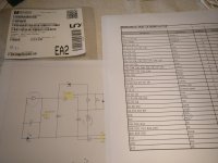
Follow the BOM, I had to make a few adjustments.Going on, brings me to a question.
The schedule tells me for R21 to use 5k1, for R15 5k.
The BOM says, R21=4k7 and R15 = 5k1
Which should I follow? ( I did order parts listed in the BOM)
- Home
- Group Buys
- DIY TDA1541A PCB "D3"