Hi sbelyo,
No I haven't gotten around to that yet, instead i've been working on a tube IV stage from post #1301.
No I haven't gotten around to that yet, instead i've been working on a tube IV stage from post #1301.

@ryanj no problem, just thought I'd ask. I did manage to pickup 4 new old stock TDA1541A chips with the same batch numbers. I decided I'll buy the Sowter transformers as well. Once my workshop is setup by the end of the month I'll start putting something together
Hi All,
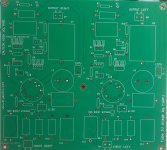
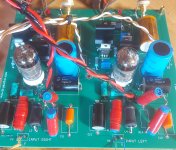
Just finished populating this tube IV stage i've been working on for the past year.
Sounding great on a PCB, I was a little bit apprehensive about using a continuous ground plane for all the return paths, but it turns out there is no issue about doing it this way at all. High current designs are probably a little more picky about this.
Still using a cap multiplier for the supply but i've got a HV shunt reg here that im going to try and see if there is any improvement.
Might do a few more measurements and post them here eventually. Much prefer just to listen... 🙂
The tube I used for this design is the 6n23p, but there are probably a whole handful of different tubes this will work with- ecc88 for example.
Ill make this PCB avaliable soon if anyone is interested.
Attachments
I'm interested in your PCB´s. If they still available, I will take all of them.
Many thanks for share your great job with the DIYAUDIO community!
Many thanks for share your great job with the DIYAUDIO community!

Nice job! I am interested in the output stage design.
I see a low resistor value of 13ohms on the input. for how many boards in parallel is this designed?
I also see some input filter with a jumper in parallel, what is this for?
I see a low resistor value of 13ohms on the input. for how many boards in parallel is this designed?
I also see some input filter with a jumper in parallel, what is this for?
Ryan,
Great work! The Salas HV Shunt reg would be great for this. B+around ~250V?
R11-R14 hand wound, very cool.
Count me in.
Cheers,
Greg
Great work! The Salas HV Shunt reg would be great for this. B+around ~250V?
R11-R14 hand wound, very cool.
Count me in.
Cheers,
Greg
Looks great Ryan. I might be tempted to pull out my transformers to try this one…and even build it myself!
Ben, thanks, I looked at the scheme and not the board. Maybe it is in schematic....It says 137V on the pcb.
E88CC, 6DJ8, 6922 are equivalent to 6n23p so lots of choices.
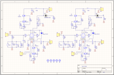
I don't see it on the schematic, but it is a nice circuit by Ryan. It has high frequency compensation for the non-oversampling high frequency droop, which can be bypassed for higher sampling rate material. One dual triode per channel for two stages: a voltage gain stage followed by an output buffer, both CCS loaded.
Thanks Supersurfer 🙂Nice job! I am interested in the output stage design.
I see a low resistor value of 13ohms on the input. for how many boards in parallel is this designed?
I also see some input filter with a jumper in parallel, what is this for?
The 13R IV is just for one 1541a chip. Output with a 13R IV with a 6n23p is about 1.8Vpp.
If the RIV (R11) is increased you will need to keep the ratio of R13 at about 50% for the nos boost filter. The filter can be bypassed if needed using J1.
The gate stoppers on the mosfets also impact the highs quite a lot. Originally I had 1k , but I found the highs to slow so decreased to 560R which seems about right in my system.
Hi Greg!Ryan,
Great work! The Salas HV Shunt reg would be great for this. B+around ~250V?
R11-R14 hand wound, very cool.
Count me in.
Cheers,
Greg
Thanks. Input V is about 137V which gives about 72.5V across the anode follower and about 64V across the cathode follower triode.
The diy wire wounds are left over from another project, ill probably end up using Rhopoints here eventually.
Thanks chromenuts, I think you might like it. I prefer it over the single ended transformer stage I implemented.Looks great Ryan. I might be tempted to pull out my transformers to try this one…and even build it myself!
Last edited:
- Home
- Group Buys
- DIY TDA1541A PCB "D3"