Hi,
I am tinkering about changing the LM317 regulators for something better.
The LM317 is not the best choice for a dac with a resolution of 16bit (or more)
The noise floor voltage of the LSB of a 16bit dac is 76uV.
The LM317 sits around 150uV peak to peak noise.
So you will never reach the 16bit resolution with this regulator.
Has anybody been experimenting with this?
The LM317 output does not go directly to the TDA1541A.
The LM317 is followed by TL431 regulators for the final voltages to the TDA1541A.
The LM317 is followed by TL431 regulators for the final voltages to the TDA1541A.
On top of that, if you feed the board with already quiet supplies you cannot improve the performance unless you believe these monolithic devices generate their own noise. Personally, I would not mess with a working D3 board at all. Experimenting should be done with your supplies and leave the board alone, it's just too easy to have a non-working dac.
@ben mah
That’s true.
Do you know the PSRR of the shunt regulators?
I would guess this will be quite low due to it’s shunt nature and the ripple from the LM317 will not be blocked and go directly to the dac pin.
That’s true.
Do you know the PSRR of the shunt regulators?
I would guess this will be quite low due to it’s shunt nature and the ripple from the LM317 will not be blocked and go directly to the dac pin.
On top of that, if you feed the board with already quiet supplies you cannot improve the performance unless you believe these monolithic devices generate their own noise. Personally, I would not mess with a working D3 board at all. Experimenting should be done with your supplies and leave the board alone, it's just too easy to have a non-working dac.
A big part of the audio hobby for me is trying to get the best out of each design.
I like the D3 but it is not the best that I have built and I feel it can be better with the right attention.
Experimenting with C19 and C22 has delivered quite different sound signatures so in this area of the dac design there is quality to gain.
The TL431 is not a stand-alone regulator. The noise floor of a TL431 regulator circuit is dependent on its supporting components and circuit design.
I am sure Ryan spent a lot of time and effort, with Spice simulations and prototypes, to be sure that his design of the power supplies is appropriate for the TDA1541A's abilities.
I am sure Ryan spent a lot of time and effort, with Spice simulations and prototypes, to be sure that his design of the power supplies is appropriate for the TDA1541A's abilities.
Hi,
I am tinkering about changing the LM317 regulators for something better.
The LM317 is not the best choice for a dac with a resolution of 16bit (or more)
The noise floor voltage of the LSB of a 16bit dac is 76uV.
The LM317 sits around 150uV peak to peak noise.
So you will never reach the 16bit resolution with this regulator.
Has anybody been experimenting with this?
Hi!
When I was buldng the D2 I attempted to take some noise measurments of the shunt regs:
https://www.diyaudio.com/forums/digital-line-level/275263-tda1541a-diy-pcb-distinction-1541-v2-12.html#post4707306
https://www.diyaudio.com/forums/digital-line-level/275263-tda1541a-diy-pcb-distinction-1541-v2-13.html#post4709996
LM317 noise is handled by the TL4131 with the pass PNP reasonable well I think. It could be done better im sure, but considering cost and complexity I think its shows decent performance.
Have fun with your tinkering! 🙂
I think a CLC power supplies would be noticeable.
I have used chokes extensively in my dacs but not yet on the D3 design. It is now powered from a Salas ultrabib (almost the usual suspect for PS design at diyaudio 😀)
Hi Ryan,
Nice to see those measurements, that looks better than I had anticipated!
I had someone with more power supply knowledge than me look into the design and this is what he wrote me.
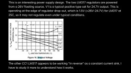
Hi there Supersurfer,
I appreciate you uploading that info- I think your friend is absolutely correct, an input voltage set to 26V is a tad to close to the drop out of the regulator. I think this issue is related to my error of initially setting the regulator voltage too high and as a result was practically doing nothing except passing current with a very low resistance... Now that the voltage is set to a more appropriate level (R21 changed from 5k1 to 4k7) the input voltage can be increased because of less voltage drop across CC1. I've just tested an input voltage of 27V and neither V1 or CC1 are getting hot. As for the SQ- I don't think it made much difference but its worth doing properly. Thanks again for bringing this up.

Hi Ryan,
You’re welcome. I try to understand your design and look for the best way to squeeze the last bits out of it. Your D3 is one of the pearls here at diyaudio and for me an easy way to get at a high level with a TDA1541A dac. It is way better than my own previous perfboard design and I also cannot find any other designs that I would judge as superior.
So please do not take my enquiries as critics on your design but as a way to jointly get the best out of our hobby.
Regards,
Hi Supersurfer,
No problem at all, im sure there are many areas in the design that could be improved upon, so enjoy the tweaking! 🙂 Please feel free to share your findings here, its interesting to see what kind of results people are getting.
No problem at all, im sure there are many areas in the design that could be improved upon, so enjoy the tweaking! 🙂 Please feel free to share your findings here, its interesting to see what kind of results people are getting.
4 x D3 update
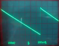
Hi All!
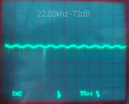
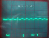
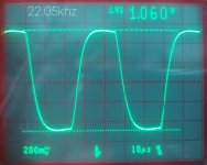
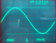
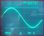
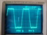
I've attached some oscillograms of my latest adventures with the TDA1541A (4 chips) running balanced into the Sowter 1465 transformers.
For IV conversion I have 4 x 13R hand wound CuNi44 resistors. The secondaries are in series with a load of about 20k (33k resistor // DCB1 input of 47k) To lower the ringing/overshoot I used about 700pF and 10k in series across the secondaries - still adjusting this.
So far this is the best result i've had with output transfomers, the sound is very natural with no fatigue.
Edit: Source files were all running at 44.1k
Hi All!
I've attached some oscillograms of my latest adventures with the TDA1541A (4 chips) running balanced into the Sowter 1465 transformers.
For IV conversion I have 4 x 13R hand wound CuNi44 resistors. The secondaries are in series with a load of about 20k (33k resistor // DCB1 input of 47k) To lower the ringing/overshoot I used about 700pF and 10k in series across the secondaries - still adjusting this.
So far this is the best result i've had with output transfomers, the sound is very natural with no fatigue.
Edit: Source files were all running at 44.1k
Attachments
-
 Untitled.jpg339.1 KB · Views: 171
 -
 20211002_160333.jpg216.2 KB · Views: 167
 -
 20211002_160200.jpg382.3 KB · Views: 160
 -
 20211002_155305.jpg362.4 KB · Views: 155
 -
 20211002_155227.jpg375.1 KB · Views: 160
 -
 20211002_154844.jpg448.9 KB · Views: 353
 -
 20211002_154738.jpg951.7 KB · Views: 368
 -
 20211002_154645.jpg405.4 KB · Views: 358
 -
 20211002_154549.jpg344.5 KB · Views: 364
 -
 20211002_154438.jpg324.8 KB · Views: 367
Last edited:
Ryan,
Very cool! The distortion products look very benign, however, I do think that they mildly contribute just enough to make this the most enjoyable dac I have ever heard. You hear deeply into the recording, with essentially the same detail as my ES9018, but with a much wider presentation. They both use hybrid IV OPSs, discrete class A to tube, and I have excellent,overkill, quite power supplies.
That is the key here, in addition to output stage, try different power supply schemes. A tube rectified C-L-C-L-C sounds better to me than silicone diodes. Try it!
Hi Ryan,
These measurements look very good. What is the bandwidth of your scope?
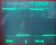
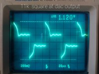
The square wave output marked dac is the dac output at the iv resistor?
I understand you use the iv resistors on the primary side of the transformers. I connected them on the secondary side, (Also sowter 1465) this seems to be a better way (havent’t tried primary though), did you experiment with both positions?
I am also interested in your damping capacitor for the overshoot, what is the audible difference?
Kind regards,
These measurements look very good. What is the bandwidth of your scope?
The square wave output marked dac is the dac output at the iv resistor?
I understand you use the iv resistors on the primary side of the transformers. I connected them on the secondary side, (Also sowter 1465) this seems to be a better way (havent’t tried primary though), did you experiment with both positions?
I am also interested in your damping capacitor for the overshoot, what is the audible difference?
Kind regards,
Ryan,
Very cool! The distortion products look very benign, however, I do think that they mildly contribute just enough to make this the most enjoyable dac I have ever heard. You hear deeply into the recording, with essentially the same detail as my ES9018, but with a much wider presentation. They both use hybrid IV OPSs, discrete class A to tube, and I have excellent,overkill, quite power supplies.
That is the key here, in addition to output stage, try different power supply schemes. A tube rectified C-L-C-L-C sounds better to me than silicone diodes. Try it!
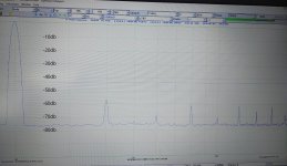
Thanks Greg,
To be honest I dont think my distorition measurments are accurate, they are very inconsistent - when I change the input voltage range the harmonics change completely, H2 goes down to -70dbr, and H3 goes up to -50dbr. Also the noise floor changes depending on the settings. So im thinking my results are not reliable, Ill have to see if I can upgrade to a USB sound interface and install REW to see if I can get some meaningful measurments.
Hi Ryan,
These measurements look very good. What is the bandwidth of your scope?
The square wave output marked dac is the dac output at the iv resistor?
I understand you use the iv resistors on the primary side of the transformers. I connected them on the secondary side, (Also sowter 1465) this seems to be a better way (havent’t tried primary though), did you experiment with both positions?
I am also interested in your damping capacitor for the overshoot, what is the audible difference?
Kind regards,
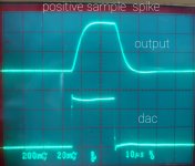
Hi Supersurfer,
My scope is 350mhz, but the leads im using are 100mhz. The measurments above are all 20mhz band width limited.
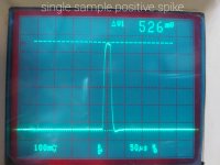
Yes, the pic labled dac is what was at the dac output with 13R IV resistor. When only a load resistor is used on the secondaries (without an IV resistor on the DAC outputs) there is much more voltage on the dac output. When I tested with a square wave there was a 1Vpp spike on the DAC outputs (attached pics). This doesnt happen very often when playing music but it did concern me considering that the output compliance of the DAC is +-25mV.
The damping cap I used caused phase shifting (smeared sound stage that sounded nauseating), so I removed the cap, changed the IV to 25R, changed the secondary windings from series to parallel and changed the load to 10k. So far this sounds like a good balance.
Attachments
Last edited:
Thanks for your explanation.
The Sowter datasheet explains how to use the IV resistor on secondary side. It needs to be dimensioned to give the right impedance for the dac on primary side.
I use the 1465’s with secondary in parallel and IV on secondary. In this way there is also an advantage that the output impedance is lower so it can drive my input volume transformers directly.
Regards,
Hi Supersurfer,
Yes I see your point - with your setup you need the current drive, but my concern is the impedance the DAC sees under the conditions as in my previous post (full current delivery in one sample). I'm really not sure if this is something to be concerned about as i haven't seen this occur in music I've observed on the scope. Maybe this is more of an issue when running at 44.1k.
As for the sound impressions - changing to IV resistor has made a positive impression on me so far, ill have to do a bit more listening but I think I have noticed an apparent increase in detail and transparency.
Last edited:
- Home
- Group Buys
- DIY TDA1541A PCB "D3"