Trust me when I tell you that you will want to be able to quickly disconnect the D3 and the converter board. So, solder on one side is fine, but not on both.
As a rule, I don’t solder any signal or power cabling in my projects, I’m always tweaking and reconfiguring components. Soldered connection is too permanent for me 😛
Good news to report!!
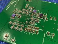
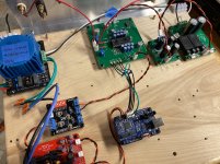
I couldn’t wait for the rest of the capacitors and two resistors to arrive but I had enough parts on the board to power up safely.
Vital Specs:
Pin 15 = -15.02v
Pin 26 = -5.006v
Pin 28 = 5.009v
Offset
AOR1 = 0mV
AOL1 = 7mV
Unfortunately, I have to wait for first sound until I receive the u.fl cables
The TDA1541A does get warm, is that normal?
(45°C hit with infrared thermometer)
Attachments
Ok, she’s warm but not hot, Thanks ernesternest.
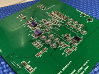
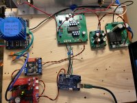
The rest of my parts arrived today and the ‘D3’ is fully populated now. All voltages are right where they should be.
I still can’t play music until the u.fl cables arrive.
Can the dc offset be trimmed properly without an input connected? I run out of turns on the trimpots at approximately 55mV and 34mV.
Attachments
@Vunce "Can the dc offset be trimmed properly without an input connected?"
I wasn't able to. Once all connections were made it was fine and 0mv offset was reached easily. I never did hear if this was correct behavior or some fault. Both of the boards I built exhibited this behavior and both work well otherwise.
Mark K.
I wasn't able to. Once all connections were made it was fine and 0mv offset was reached easily. I never did hear if this was correct behavior or some fault. Both of the boards I built exhibited this behavior and both work well otherwise.
Mark K.
PCBs
Thanks to everyone that put their name down on the list for a D3 PCB. Nice to see there is still some interest in the D3 PCB and ye old TDA1541A.
I'm going to go ahead and order the D3 PCBs this week. Should get them in a week or two.
Shipping at the moment is a bit problematic due to reduced planes in the sky and there are a number of countries that regular economic postage cannot get to - there are other options but they are 10 times the price. Ill find out exactly which countries this affects and report back.
Thanks for the update Ryan.
galloween / 1
asanden / 3
damiangt3 / 2
advr / 2
Myint67 / 3
Mituisho / 2
ggetzoff / 2
pwagner / 2
TioFrancotirador / 4
obh / 2
Raimundas / 2
bogdandascalu87 / 2
Aguaazul / 2
resets / 2
goody75 / 4
zeroalbedo /4
kenlaumm / 2
galloween / 1
asanden / 3
damiangt3 / 2
advr / 2
Myint67 / 3
Mituisho / 2
ggetzoff / 2
pwagner / 2
TioFrancotirador / 4
obh / 2
Raimundas / 2
bogdandascalu87 / 2
Aguaazul / 2
resets / 2
goody75 / 4
zeroalbedo /4
kenlaumm / 2
galloween / 1
asanden / 5 (some extra for a nice person who gave me two A's)
damiangt3 / 2
advr / 2
Myint67 / 3
Mituisho / 2
ggetzoff / 2
pwagner / 2
TioFrancotirador / 4
obh / 2
Raimundas / 2
bogdandascalu87 / 2
Aguaazul / 2
resets / 2
goody75 / 4
zeroalbedo /4
kenlaumm / 2
asanden / 5 (some extra for a nice person who gave me two A's)
damiangt3 / 2
advr / 2
Myint67 / 3
Mituisho / 2
ggetzoff / 2
pwagner / 2
TioFrancotirador / 4
obh / 2
Raimundas / 2
bogdandascalu87 / 2
Aguaazul / 2
resets / 2
goody75 / 4
zeroalbedo /4
kenlaumm / 2
galloween / 1
asanden / 5 (some extra for a nice person who gave me two A's)
damiangt3 / 2
advr / 2
Myint67 / 3
Mituisho / 2
ggetzoff / 2
pwagner / 2
TioFrancotirador / 4
obh / 2
Raimundas / 2
bogdandascalu87 / 2
Aguaazul / 2
resets / 2
goody75 / 4
zeroalbedo /4
kenlaumm / 2
BDL / 1
asanden / 5 (some extra for a nice person who gave me two A's)
damiangt3 / 2
advr / 2
Myint67 / 3
Mituisho / 2
ggetzoff / 2
pwagner / 2
TioFrancotirador / 4
obh / 2
Raimundas / 2
bogdandascalu87 / 2
Aguaazul / 2
resets / 2
goody75 / 4
zeroalbedo /4
kenlaumm / 2
BDL / 1
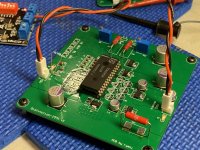
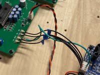
I received the U.fl cables (Thanks Greg 😉) and promptly attempted to attached Molex crimps for KK Series connectors at the JLSounds I2SoverUSB end. This step took much longer than anticipated because these cables are extremely delicate. Connecting the ground braid to a Molex crimp was nearly impossible, so I aborted that idea. Instead I used a piece of CAT5 24awg copper wire bent in a ‘U’ shape and soldered that between BCK and DL ground pads. Then soldered a single 22awg copper stranded wire to the CAT5 to attach to the I2SoverUSB board.
The u.fl cables carry signal only with a separate single wire for ground connection.
Once that hurdle was passed it was clear sailing, drama free power up with sweet music as the result! The boards are set up for simultaneous input. At the moment, I’m using the stock, onboard I/V conversion with 100R PRP resistors.
A note about dc offset trimming, it only trims to 0mV when the inputs are connected. Thank you Mark K. for this information!!
A request for the next GB,
In my situation using the u.fl cables was a real pita. There is no benefit to use these cables if all of the connectors in the chain are not the same. There is plenty of real estate available to add a redundant set of inputs that use a standard header/connector setup. I know Ryan said no revisions will be made, but I think this addition would simplify hook-up for many builders.
Other than the “cabling”, this was a very satisfying and fun build. The psu is a bit different but works perfectly and is rock solid. I was able to go as low as 24vdc until it fell out of regulation. And best of all it’s dead silent at idle and sounds GREAT!! It can only get better with I/V tweaking, hehe!
Thanks for sharing this Dac, Ryan 🙂
Cheers,
Vunce
Attachments
galloween / 1
asanden / 5 (some extra for a nice person who gave me two A's)
damiangt3 / 2
advr / 2
Myint67 / 3
Mituisho / 2
ggetzoff / 2
pwagner / 2
TioFrancotirador / 4 + 1 x "conversion PCB" if possible
obh / 2
Raimundas / 2
bogdandascalu87 / 2
Aguaazul / 2
resets / 2
goody75 / 4
zeroalbedo /4
kenlaumm / 2
BDL / 1
I am using 65 Ohm with no other gain stage. My preamp has enough gain.
ecdesigns used 150 Ohm in this post #6077:
Building the ultimate NOS DAC using TDA1541A
ecdesigns used 150 Ohm in this post #6077:
Building the ultimate NOS DAC using TDA1541A
Thanks Ben Mah,
I have 100R's currently installed, I'm going to try dropping down to something in the 50-65R range.
I'm using my preamp set-up to drive zero gain amplifiers, so it's got plenty of oomph 😀
I have 100R's currently installed, I'm going to try dropping down to something in the 50-65R range.
I'm using my preamp set-up to drive zero gain amplifiers, so it's got plenty of oomph 😀
I’m hopeful that Ryanj has a positive experience with Bisek’s transformers as I’m interested in that option also.
Hi Ryanj,
Would increasing the total onboard current draw to approximately 190mA from tapping off the +/-5v rails to power an I/V circuit be possible?
Would increasing the total onboard current draw to approximately 190mA from tapping off the +/-5v rails to power an I/V circuit be possible?
Hi Ryanj,
Would increasing the total onboard current draw to approximately 190mA from tapping off the +/-5v rails to power an I/V circuit be possible?
Hi Vunce,
The onboard reg is supplied by a CCS so you will have to lower the value of R22 to increase the current.
I have a feeling it will compromise the performance. Just watch the temp of CC1 and V1. Will you be powering a CCS? if its a dynamic load it may not be a good idea.
Well done on your build so far

Last edited:
Thanks Ryan!
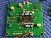
I wanted mimick the OPA861 output stage of the Aya Dac for another project with your Dac in mind also. My output stage has an onboard regulator, I would have bypassed it if I was going to tap into the D3 psu. But I don’t think that is a good idea. Probably should have it’s own power supply. I do want to try and integrate the onboard DC nulling circuit though.
I wanted mimick the OPA861 output stage of the Aya Dac for another project with your Dac in mind also. My output stage has an onboard regulator, I would have bypassed it if I was going to tap into the D3 psu. But I don’t think that is a good idea. Probably should have it’s own power supply. I do want to try and integrate the onboard DC nulling circuit though.
Attachments
Last edited:
- Home
- Group Buys
- DIY TDA1541A PCB "D3"