galloween / 1
asanden / 3
damiangt3 / 1
advr / 2
Myint67 / 1
Mituisho / 2
ggetzoff / 2
pwagner / 2
TioFrancotirador / 4
obh / 2
Raimundas / 2
bogdandascalu87 / 2
Aguaazul / 2
asanden / 3
damiangt3 / 1
advr / 2
Myint67 / 1
Mituisho / 2
ggetzoff / 2
pwagner / 2
TioFrancotirador / 4
obh / 2
Raimundas / 2
bogdandascalu87 / 2
Aguaazul / 2
This interest list is for dual/balanced board?galloween / 1
asanden / 3
damiangt3 / 1
advr / 2
Myint67 / 1
Mituisho / 2
ggetzoff / 2
pwagner / 2
TioFrancotirador / 4
obh / 2
Raimundas / 2
bogdandascalu87 / 2
Aguaazul / 2
There will probably not be a dual board. It will be a D3 with revised power supply layout for easier assembly.
This interest list is for dual/balanced board?
Hi pistollero,
I wont be designing a new board at this stage, just a new small revisions of the original D3 PCB, such as resizing a few small footprints to make them easier to solder, but I wont be altering the layout.
galloween / 1
asanden / 3
damiangt3 / 1
advr / 2
Myint67 / 1
Mituisho / 2
ggetzoff / 2
pwagner / 2
TioFrancotirador / 4
obh / 2
Raimundas / 2
bogdandascalu87 / 2
Aguaazul / 2
resets / 2
asanden / 3
damiangt3 / 1
advr / 2
Myint67 / 1
Mituisho / 2
ggetzoff / 2
pwagner / 2
TioFrancotirador / 4
obh / 2
Raimundas / 2
bogdandascalu87 / 2
Aguaazul / 2
resets / 2
galloween / 1
asanden / 3
damiangt3 / 1
advr / 2
Myint67 / 1
Mituisho / 2
ggetzoff / 2
pwagner / 2
TioFrancotirador / 4
obh / 2
Raimundas / 2
bogdandascalu87 / 2
Aguaazul / 2
resets / 2
goody75 / 4
asanden / 3
damiangt3 / 1
advr / 2
Myint67 / 1
Mituisho / 2
ggetzoff / 2
pwagner / 2
TioFrancotirador / 4
obh / 2
Raimundas / 2
bogdandascalu87 / 2
Aguaazul / 2
resets / 2
goody75 / 4
10 gone, 9 left. The very last ones I have. 🙂
Mine arrived today in California USA. Thanks Thaun.
Aguaazul
Hi all,
I’m ready to move forward with my D3 after finally sorting out a Shigaclone transport project.
I’m glad to finally have a functioning digital source again after struggling with my failing Rotel 855 for a while. I do still miss it and the sound of its TDA1541A.
This is my first DAC project. I’m temporarily using a SMSL M8 with the transport as a band aid for now.
I’ve been using the thread search to try and find answers to questions I have about building the D3 and taking notes.
The multiple power supplies required to deal with the D3 and other boards I will need to use a SPDIF source are a little more complex than I’m used to.
That doesn’t take into consideration that I would also like to be able to stream music from a computer through the D3 at some point.
I’m considering a used Mac Mini server as a media storage solution. It would actually directly integrate with the setup I’m planning as it already has a 3.5mm digital out capability that only requires a mini to toslink cable.
To get this project off the ground I’m trying to think of ways to keep it as simple as possible without making any major compromises to its potential performance.
I ordered the D3, I2S to Sim and Cap Multiplier boards assembled from Ryan this past Xmas. That way I have known tested/working boards.
I won’t be using the I2S to Sim board to start with as I don’t have the extra U.FL coaxial cables to connect it on hand right now.
Since the transport seemed like the simplest source to start with, but only has an SPDIF output, I looked around for options to deal with the SPDIF to I2S conversion.
There were several receiver boards on eBay. Twisted Pear had one. Then there was Ian’s FIFO project which has been through several iterations.
I came across a used first generation Ian’s FIFO with the SPDIF board and upgraded reclock in the swap meet and decided to buy it. I can select between a Coax and Toslink input, so that will allow for using the transport and another optical digital source.
I’m starting with getting the basics of the power supplies sorted.
The main FIFO board requires a 6V supply, whereas the SPDIF and reclock use 5V. However, as far as I can tell, the main FIFO will power the SPDIF and reclock boards with the option of seperate supplies for all three. I will be starting by powering everything from the FIFO so I’ll need one additional 6V supply for that.
While building my Shigaclone I had attempted to utilize a Salas SSLV as a power supply. Unfortunately, the current demands of the transport while executing the TOC read process required me to set the SSLV so that it was producing almost 800ma. It became unrealistic for me to properly sink its transistors and still have a fairly compact supply design. I resorted to a simpler design using a LM7808 equivalent.
So I have one functioning SSLV that I can reset the current on and adjust the voltage to 5V for the D3.
According to a previous post the supply current requirements were:
26V - 140mA
5V - 20mA
I will probably set the 5V SSLV at about 100ma in case I find I need to some more current to power other boards.
I’m going to populate a second SSLV and set it at 6V for the FIFO/reclock/SPDIF assembly. I’m not sure what the current demands for the three are. If anyone has some experience powering this combination with the SSLV I’d appreciate some input.
Both SSLVs will be powered by a single Antek AS1212 with dual primaries and secondaries...one for each.
I’m currently trying to set up and test another transformer I have on hand with the hopes of using it for the 26V on the D3. It is a surplus unit I got from ApexJr. It has a single primary and dual secondaries. It produces about 25.5 - 26V AC per secondary unloaded depending on time of day and mains voltage.
Since Ryan designed the cap multiplier board for a 24V center tapped unit I wasn’t positive as to the proper hook up.
A search turned up some discussion earlier in the thread about tranny wiring to the CapMx and voltage testing with a load on the output as well as testing voltages on the D3 before installing the 1541.
Markos4553 posted that he used a Triad Magnetics VPT48-520 on his project and showed a pic of his test bed.
I had recently used some of the Triad transformers for the Shigaclone and a phono amp and recognized the color coding of the wiring. I looked up the data sheet and it appears he wired the secondaries in series and used the connecting point between the two secondaries as the center tap connection.
Other research online points toward this method of using dual secondary transformers in center tap applications like this.
In my application, wiring the secondaries in series would give ~25.5V across each secondary to the center tap point where they are joined and about 50V across both secondaries.
I just want to confirm this is the correct way to wire this transformer to the CapMx.
I realize I will have to also test voltage output with a load and through the D3 and that this transformer may come up a little short.
I am hoping I can reduce the value of R4 and R5 on the CapMx to get the 26V I need.
One other question I have is regarding the D3 iv resistors and an output stage.
I have only read a little bit regarding how the iv resistors affect the output level and how to gauge if you have enough gain in your system to not use an output stage.
My Shigaclone appears to have a very high output level in my system even though I utilized resistors on its digital output as outlined in the build threads I came across. I am using Vishay MKP 110/330 to ground and signal. The output level is so high that I barely have to turn the volume pots on my preamp up to get a normal listening level.
My preamp is based on Salas’ DCB1 but was modified with Jensen transfomers on the output to pick up 6dB of gain to match better with the requirements of my analog front end.
I have had other CD players hooked up to this system, and although the gain level is always higher, it is not nearly as high as the Shigaclone. I haven’t figured out yet how or if I need to modify the values of the output resistors to reduce the output level from the Shigaclone.
I thought this issue might be related to the gain level or adjustment of the SMSL M8 I am currently using. There is no hardware gain adjustment in the M8.
I hooked up my PC via USB to the M8 and found that while streaming music through Foobar2K there was a software gain adjustment. However, I was able to leave it maxed out without having any issues. The preamp appeared to need normal adjustment of the pots when the computer was used as a source through the M8.
So I am questioning what to do to address this issue?
Will this extra gain be useful if I want to try simplifying this project by eliminating the need for an output stage?
Will it just complicate things further since my computer based digital source will always be much lower than the Shigaclone and they both would be connected to the D3?
I was able to come up with some CEN/SEN output stage boards and I have the jfets to populate them. That would require yet another power supply which if possible I’d like to avoid for now. I’d rather resort to a transformer iv stage if I really needed more gain.
Attachments
Sorry for that novel.
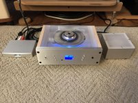
I had some time this afternoon, and was feeling cocky, so I wired the surplus tranny up to the CapMx with the secondaries in series as I described.
I put two 100 Ohm 5 Watt resistors in series on the DC output of the CapMx and gave it a go.
Voltage stabilized at just over 26V.
Pure dumb luck!
I guess the next step is to set up a SSLV for 5V and then test for correct voltages on pins 15, 26 and 28?
Attachments
Sorry for that novel.
I had some time this afternoon, and was feeling cocky, so I wired the surplus tranny up to the CapMx with the secondaries in series as I described.
I put two 100 Ohm 5 Watt resistors in series on the DC output of the CapMx and gave it a go.
Voltage stabilized at just over 26V.
Pure dumb luck!
I guess the next step is to set up a SSLV for 5V and then test for correct voltages on pins 15, 26 and 28?
Hi chromenuts,
I've tested all the voltages and i've had your board playing music with the i2s2sim PCB, dont power it up without a 1541 chip installed or a dummy load. If you want to use I2S first without converting it then you will have to change the jumper setting on the back of the D3 PCB. The SSLV should be a good choice for the 5V supply.
galloween / 1
asanden / 3
damiangt3 / 1
advr / 2
Myint67 / 1
Mituisho / 2
ggetzoff / 2
pwagner / 2
TioFrancotirador / 4
obh / 2
Raimundas / 2
bogdandascalu87 / 2
Aguaazul / 2
resets / 2
goody75 / 4
zeroalbedo /4
asanden / 3
damiangt3 / 1
advr / 2
Myint67 / 1
Mituisho / 2
ggetzoff / 2
pwagner / 2
TioFrancotirador / 4
obh / 2
Raimundas / 2
bogdandascalu87 / 2
Aguaazul / 2
resets / 2
goody75 / 4
zeroalbedo /4
Hi Ryan,
Is it possible to order the I2S/simultaneous board together with the D3?
Regards, Albert
Is it possible to order the I2S/simultaneous board together with the D3?
Regards, Albert
Yes I still have some in stock, and I also have some i2s2sim PCBs with inverted data outputs - Ill provide info on them eventually.
Attachments
Last edited:
Hi chromenuts,
...dont power it up without a 1541 chip installed or a dummy load...
Great...
I already did for as long as it took for the CapMx to come up to voltage for me to measure the voltages and for it to discharge. There was no load. Have I damaged it by doing so?
In reading posts of others testing for voltages at the IC socket I don’t remember them mentioning putting a load on the board.
galloween / 1
asanden / 3
damiangt3 / 1
advr / 2
Myint67 / 4
Mituisho / 2
ggetzoff / 2
pwagner / 2
TioFrancotirador / 4
obh / 2
Raimundas / 2
bogdandascalu87 / 2
Aguaazul / 2
resets / 2
goody75 / 4
zeroalbedo /4
Great...
I already did for as long as it took for the CapMx to come up to voltage for me to measure the voltages and for it to discharge. There was no load. Have I damaged it by doing so?
In reading posts of others testing for voltages at the IC socket I don’t remember them mentioning putting a load on the board.
Should be fine for that short amount of time. Shunt elements Q1 Q2 Q3 will get hot without a load attached, as is the nature with any shunt regulator.
- Home
- Group Buys
- DIY TDA1541A PCB "D3"