Print a waveguide for it... I know that works and here's proof 👍
https://www.somasonus.net/sb-acoustics-sb26
https://www.somasonus.net/sb-acoustics-sb26
Thank you for the update.
If I now understand correctly the new mike confirms your original data. I am still puzzled by the little wiggle though.
Depending on your Xover design and what is a sensible Xover frequency say 2-2.5Khz for the chosen drivers you could still have a reasonable first design.
As noted you can try flipping the tweeter polarity when you have the crossover built to see how both units react and which one gives the best phase match.
Do you have any components at hand to see what a 2nd order High Pass made up of say 3-8uf and 200-250mH does for the overall response as you measure frequency sweeps using the microphone.
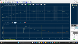
I posted an image in the thread a page or two back with a Sb26 in one of the designs, I have attached a screenshot of a measured response.
Its a while since i made that box, I will have to look back for actual Xover values used, failing that i could open the box and look at the Xover. Probably ended up as a third order. With hindsight it may have a bit two much treble and maybe nicer with another 1 or 2 ohms in the tweeter circuit. More measurements could help settle that.
As others have shown from the simulations they have provided, you have just hit a position where you have a notch at 3 KHz Some would see this as a possible advantage, it should help prevent to much ss sounds on voices and other instruments that occupy that range.
Consequently I would maybe work a bit more with this and see how it works out as you bring the Xover into play. The microphone will be a good tool that lets you see what is really happening
If I now understand correctly the new mike confirms your original data. I am still puzzled by the little wiggle though.
Depending on your Xover design and what is a sensible Xover frequency say 2-2.5Khz for the chosen drivers you could still have a reasonable first design.
As noted you can try flipping the tweeter polarity when you have the crossover built to see how both units react and which one gives the best phase match.
Do you have any components at hand to see what a 2nd order High Pass made up of say 3-8uf and 200-250mH does for the overall response as you measure frequency sweeps using the microphone.
I posted an image in the thread a page or two back with a Sb26 in one of the designs, I have attached a screenshot of a measured response.
Its a while since i made that box, I will have to look back for actual Xover values used, failing that i could open the box and look at the Xover. Probably ended up as a third order. With hindsight it may have a bit two much treble and maybe nicer with another 1 or 2 ohms in the tweeter circuit. More measurements could help settle that.
As others have shown from the simulations they have provided, you have just hit a position where you have a notch at 3 KHz Some would see this as a possible advantage, it should help prevent to much ss sounds on voices and other instruments that occupy that range.
Consequently I would maybe work a bit more with this and see how it works out as you bring the Xover into play. The microphone will be a good tool that lets you see what is really happening
Attachments
Do 15/30/45/60 degree horizontal off axis measurements. Let's see what happens to your 1KHz dip.
