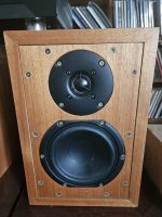
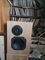
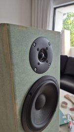
If you want a quick reality check of the importance of flush mounting. Then find a piece of cardboard and cut a hole for the tweeter, and place it on the front baffle with a piece of tape. If you use a thick tape, then you can also imitate a slight round-over as you mount the cardboard to the baffle.
Learn as much as you can from the boxes before committing to make new boxes. There is nothing wrong with adding another layer to the fronts for testing. Be shameless in using cardboard, foam, tape--whatever you have. Take time to listen to changes before you measure them. You already know more than you give yourself credit for, and we all must start somewhere. If you start over, know that you are neither the first nor last person to destroy cabinets 🙂 Sometimes acceptance of throwing one away is a good plan for fastest development free of constraints.
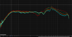
Done testing the tweeter with some cardboard, so it acts like flush mounted.
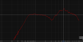
There are improvement on the 3khz area and the lower end get a bit more body i guess..
For the peak around 4k to 10k might be the RTA Mic , the mic is not calibrated , just some cheap mic without any calibration file / data.. But i'm not so sure..
Definitely will flush mount the tweeter and do some more round over..
The red one is the new frequency response
But i think the crossover trial end error will be much more harder? Matching the phase and get the flattest response...
You still have to match the phase correctly in a 2-way, the difference is that you can use gated measurements with far-field response much more easily in a 2-way, eliminating a lot of additional complexity, like summing the near-field with baffle step calculations.
I cheat almost always, in that I use far-field in-room for a lot of work better builders might not.
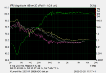
Have you done near-field? Like 5mm away from the tweeter to compare with?Done testing the tweeter with some cardboard, so it acts like flush mounted.
Here is the near field measurements.. The spl adjusted to match the level..You still have to match the phase correctly in a 2-way, the difference is that you can use gated measurements with far-field response much more easily in a 2-way, eliminating a lot of additional complexity, like summing the near-field with baffle step calculations.
I cheat almost always, in that I use far-field in-room for a lot of work better builders might not
The Blue is the near field measurement.. Is this looks normal?
Real near field measurement will usually not give you the correct response. Specially not in the high registers. Try 5-10 cm instead.
You have however removed the influence of diffraction and caught some of the drivers character.
Look at this measurment that is done professionally.
https://hificompass.com/en/speakers/measurements/sbacoustics/sb-acoustics-sb26adc-c000-4
You have the same dips and peaks in you measurement but more pronounced.
You certainly clearly have shown how important it is to reduce diffraction as much as possible by flush mounting the tweeters surface with the baffle surface and keep cabinet edges rounded.
Last edited:
The Blue is the near field measurement.. Is this looks normal?
This is really useful. The difference at 3K can be attributed to the cabinet. Above 10k I imagine is due to the phase plug (cover) on the tweeter. Your mic is too close to pick up the full radiation pattern. That's fine, what we care about in assessing the issue is the 3k dip. @flex2 is probably right that you'll want to re-measure at further afield with gated measurements later on to re-assess, but in terms of answering the question about your 3k dip, you now have your answer. 😉
Here are some results of reduced diffraction because of added distance to one of the edges. In this case the top edge.
All edges have 25mm rounding.
The original design have 120 mm between the center of the dome to the side edges and the top edge, and that rendered in quite much diffraction.
Then I added more distance to the top edge by extending the baffle with +50, +75 and +100 mm of baffle.
So 170, 195 and 220 mm between centre of dome to top edge, while distance to side edges remained at 120 mm.
Here some added distance to top edge improved linearity by reducing diffraction or linearize diffraction as a consequence of selecting a different distance to top edge compared to side edges.
Purple +50mm
Blue +75mm
Yellow +100mm
So don't be afraid to have some distance to the top edge.
Curves scaled by 3dB for visual reasons.
I must admit it I didn't realise diffraction effects could compound so badly. I need to make a note to self to always flush mount the tweeter and keep it away from the top edge unless you have modelled its characteristics.
I like the sound of the SB 19 dome in an offset position which also helps to break up the diffraction effect, and as they are mirror imaged you can either have the tweeter on the outside or inside depending on room or which sound best to your ears.
The phase plate looks fine, I asked the question just to make sure it handed been banged or was touching the dome.
With a bit of ingenuity you should be able to attach a piece of wood behind the tweeter cut-out using a pinner or some glue and then add a circular piece of wood to allow a new centre hole to be drilled to align a router jig to cut a flush rebate for the tweeter.
Attachments
Do off axis measurements. See what the dip looks like then.... do 15,30,45,60,75 off axis measurements.
Did you hear me? ....
post an off axis measurement.... 🙂 Then see what happens to your dip
This is why many speakers favour waveguides these days. A waveguide can largely "hide" baffle edges meaning diffraction responses that change with axis are greatly reduced.
Did you hear me? ....
post an off axis measurement.... 🙂 Then see what happens to your dip
This is why many speakers favour waveguides these days. A waveguide can largely "hide" baffle edges meaning diffraction responses that change with axis are greatly reduced.
Hello.. Just updated the baffle.. I just have the time to do it recently..
Somehow i lost my previous measurement so i can't overlay it. The dip is better but not much .still the same, but the low end below 2k got some boost there..
I still don't know what causes the peak on the 6k region, i tried to put extra thickness at the top baffle, and other baffle" tweak. but nothing works..
Also the round over is now 0,75inch..
Attachments
Wait... Am I missing something? That measument looks exactly like the midrange... Not the tweeter 🤔
I invite you to use the excel file from this address.
http://audio.claub.net/software/jbabgy/BDBS.html
http://audio.claub.net/software/jbabgy/BDBS.html
Any diffraction effects become apparent when measuring the polars. Like said above, perform off-axis in incremental steps of 10 degrees. You’ll need those anyway for your design.
As shown, the ADC does pretty well, enclosed measurement was done at 30cm on a test baffle of 60x75cm. It’s essentially showing the limits of my (old) measurement gear that I changed afterwards because of this graph…
As shown, the ADC does pretty well, enclosed measurement was done at 30cm on a test baffle of 60x75cm. It’s essentially showing the limits of my (old) measurement gear that I changed afterwards because of this graph…
Attachments
So diffraction (from the tweeter frame) is the culprit. I suspect your mike displays a rising top end (like many uncorrected do) too. Either do a test drive with the ADC flush mounted on a bigger baffle or try another mike.
Flush mount and round overs wont do much.
Can be measured, but basic smoothing removes most of it.
Or to word more precise, not flush mounting and minimal round overs.
Would not create that 3k dip. Or response
A small baffle, with equal spacing from almost 3 edges would.
Could already tell this is pretty normal skinny baffle response with the tweeter mounted dead middle.
Saw binding magic angles would basically make it worse.
My virtual cad simulation matches the dip close enough.
SB data sheet usually worthless, so you have to compensate in simulation.
maybe test on IEC baffles but almost always nearfield or not at 1 meter standard.
Most the datasheets are misleading.
Your data from measurement doesn't seem to be displaying correctly.
The response is close but how it displays in dB scale doesnt seem right.
Not sure if your testing also with a cap or applying a filter
it seems to be around 600 Hz so it will change the lower response of tweeter.
To remove the 3k dip the tweeter needs to be offset to one side.
To remove it completely it is impossible. Because the baffle is too small or not wide
enough. I can offset enough in sim according to the driver SD....But real world
the mounting flange or bezel is physically too large.
Seems a slightly more accurate model predicts most the response expected
of a small baffle with centered tweeter. And making the baffle wider and off settting
driver to one side. actually creates a flat response. not flush mounting and minimal round overs
is not the problem, since real world room response exceeds these by a landslide.
- Home
- Loudspeakers
- Multi-Way
- Diy Speaker SB16PFCR and SB26ADC 2 way floorstanding, Help with Crossover and Measurements ...
