How does the project called on this PCB site? [Is it shared?] 😎Thanks for the explanation. My boards from JLCPCB. are on the way as evidently are the parts from Mouser and Digi-Key. I should have lots of boxes land on my doorstep in the next few days….
Is there anything that can do done to tune the distortion characteristics? Or is it mainly dependent on the characteristics of the VFET?
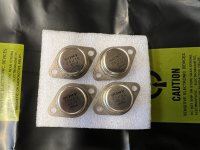
Treats arrived… came from fellow DIY member in swap meet
Not matched…tested by seller using SONY service bulletin as guide
Not ready to jump in yet, but wondering what (if any)other basic testing I should do before proceeding to build with them?
I’ve the SONY service bulletin no. 49 & 62 to look over…and confirm they’re functional
Not matched…tested by seller using SONY service bulletin as guide
Not ready to jump in yet, but wondering what (if any)other basic testing I should do before proceeding to build with them?
I’ve the SONY service bulletin no. 49 & 62 to look over…and confirm they’re functional
Attachments
just chill and wait ....... to get inspiration what to build
test them simple or in complicated way ....... don't bother about rank, at least when Papamps are in question
he made them so all can jump in
test them simple or in complicated way ....... don't bother about rank, at least when Papamps are in question
he made them so all can jump in
My luck proceeds. I have ordered three internal SMPS over the last six weeks for my Sony TA4650 hot rod attempt, all three don't work (Amazon Mean Well). I couldn't believe the first one was a dud, I thought the second one must be a fluke, but the third one not working must be a message from the DIY gods to do something else.
Yes, I tested the crap out of them and they just plain will not take a measured 120 V AC from the wall and emit the 36V output. I made a special cord and rig, hooked everything up according to You Tube video, they just are all three duds. I know, everybody will say that it is impossible, but it happened according to my wonderful DIY karma. The 20V SMPS for the preamp hooked up and worked like a charm immediately.
Anyway, I am going to order an external SMPS instead. With a variable power supply, both VFET boards work, bias easily. and make nice sound, I have all the wiring attached to the transistors on the heat sinks ready to wire when ready. At any rate, the external SMPS will allow more chassis room for cards. Just needs the viable power supply and soldering everything together, I hope.
What were the current ratings of the supplies, and were you trying to charge a bank of capacitors as well?
I wasn't charging anything, just bench testing and measuring. They were all Mean Well LRS 150-36. 4.3 A, I presume, @36V DC. The LED never lit up on any of them when attached to 120V AC on the input. I was very careful hooking the input up the right way.
Don't know if Amazon got a bad lot, they were all from Amazon. The 20V SMPS that works fine with the preamp was purchased through ebay.
I'll just order one of the external ones. I know that it seems like quite a streak, especially since the Mean Wells seem to have a good reputation.
Don't know if Amazon got a bad lot, they were all from Amazon. The 20V SMPS that works fine with the preamp was purchased through ebay.
I'll just order one of the external ones. I know that it seems like quite a streak, especially since the Mean Wells seem to have a good reputation.

Completed my Vfet with 2SK82 and Bulwark FE last night. Had a short listen tonight, the sound is definitely cleaner than the Myst TMA3 it replaced. I am waiting for the new FE Mr. Pass produced to hit the DiyStore.
Congrats! The Sony VFET OS and Mark’s FE options are DIY paradise. 😀
I was one of the very fortunate to nab a lottery amp and I’ve been Pass ClassA hooked ever since. F5, ACP+, and ACAmini followed quickly after. 😎
I was one of the very fortunate to nab a lottery amp and I’ve been Pass ClassA hooked ever since. F5, ACP+, and ACAmini followed quickly after. 😎
Any word on when these will be available in the DiyAudioStore?In addition to all the other choices, I have another new front end that will fit, and it is very cheap...

I'm pondering folding the front end: here with ECC88, but can be done with great success with for instance a 2SK30 too. (In the sims I found the 2SK170 a bit too hefty).
The bonus points: it works with the Vb=40 Volts; I made the bias simple here, but all the elaborate bias that others cam up with can be used of course.
I charge it with a choke to get a flying output, that is, it swings up and below the earth.
I have a choke like this already in my box.
My first idea was to load this on the ECC88 anode (or jFET drain), it gives a great bandwidth but imho needs feedback. Ben Mah if I remember approximately did this too.
105H - even my memory is a bit dyslectic. 😉
In fact it is even larger: 210H as measured with my LCR and parallel, Rdc=600Ω. The manufacturer says it is 235Henry per winding half. If in series the bandwidth is higher still - 200kHz, Rdc=2k5. Also important: It is low-end you gain. But 2k5 & 5 mA = a lot of loss when we are talking 40Vb.
ECC88 (in fact PCC88) is very well suited for the low voltage.
It is a 10K:10K driver amourphous core transformer, that exhibited quite some bounce on a square wave, so I never used it for my 300B. Then I tested it as choke, and there was the smoothest squarewave you can imagine. Tested the bandwidth: very high. So I have this on a plate that fits the chassis. I am now making a relais that will switch the driver modes
- I have as first test the 6SJ7. Why pentode: they exhibit some degradation in harmonics. That could fit the 2SJ28. [I know I am not qualified to determine such a result, I do have the 10K hours but in what circumstances, but I said it anyway]
- By the way. The EF89 simulates better, but I must say, the pentode models are probably not very reliable at this low voltage. I had a plan to try EF804 pentodes too. These are excellent on low voltage.
I have finished building 4 channels of 2SK82 for bi-amping and one of them is not behaving correctly. Would appreciate some advice here.
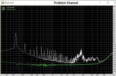
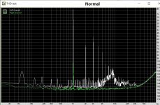
All my measurement was done directly on the VFET follower stage without any front end. 0dB on the attached graph correspond to about 6Vrms. Operating point is as stated in the manual, 1.6A current, 14V at MOSFET drain. Measurement was done at 192kHz sampling rate on an RME ADI2 Pro FSR.
First, the problem channel have a gain of > 1, at about 0.8dB. I thought all follower should be <=1. The rest of the three channel is close to unity gain.
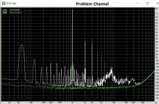
Second, the noise floor rises as frequency goes lower. There are also much higher 60Hz harmonics present in the THD measurement.
I have tried to add an LT1084 regulator, hoping that it was just a power supply noise problem, but see little to no improvement with respect to the rising noise floor and 60Hz harmonics. (measurement shown is with LT1084 in place, and bypassing the trio of 3R3 resistor on the power board to get about 33.5V at the drain of VFET).
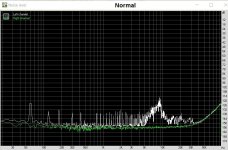
The three working channels all have similar measurement to the "normal" graphs shown.
Green trace on the graphs is an unused input measurement channel which I use as a sanity check and as a reference as the measurement noise floor
Any suggestions would be welcome.
All my measurement was done directly on the VFET follower stage without any front end. 0dB on the attached graph correspond to about 6Vrms. Operating point is as stated in the manual, 1.6A current, 14V at MOSFET drain. Measurement was done at 192kHz sampling rate on an RME ADI2 Pro FSR.
First, the problem channel have a gain of > 1, at about 0.8dB. I thought all follower should be <=1. The rest of the three channel is close to unity gain.
Second, the noise floor rises as frequency goes lower. There are also much higher 60Hz harmonics present in the THD measurement.
I have tried to add an LT1084 regulator, hoping that it was just a power supply noise problem, but see little to no improvement with respect to the rising noise floor and 60Hz harmonics. (measurement shown is with LT1084 in place, and bypassing the trio of 3R3 resistor on the power board to get about 33.5V at the drain of VFET).
The three working channels all have similar measurement to the "normal" graphs shown.
Green trace on the graphs is an unused input measurement channel which I use as a sanity check and as a reference as the measurement noise floor
Any suggestions would be welcome.
Attachments
- Home
- Amplifiers
- Pass Labs
- DIY Sony VFETs OS2 Official thread