I tend to believe Pa, especially when single sentences are in case
edit: when articles are in case, I'm expecting typo or two, deliberate or not
but, that's part of education
edit: when articles are in case, I'm expecting typo or two, deliberate or not
but, that's part of education
Last edited:
Juan , are your capacitors all already "burn in " , at least an 100 hours ??
it is well known that the Silmics need long burn in 😉
also , the higher the voltage rating the lower the ESR 😉
.
yes the Silmic had burn in as i remove it from my Dac before ... second try on the Vfet , i don't like it here too .. end of the story..😀
Is my reading correct that the 20V don't need to be adjusted and that the boards are supposed to be mounted as delivered, already fine adjusted by Papa?
That would be great news and somewhat different from some early builders which seem to adjust it...
Thanks for your confirmation!
Claude
I soldered mine in as is, and did not turn them ahead of time like some others did. When it was time to check them and adjust… they barely needed an adjustment to achieve the 20v reading.
Mine came with a 16,5v setting with the pots midway, but I think I do have high vgs devices (123 markings, or somewhere there)
My modules was adjusted to 18.8 VDC from "factory" so I gave it just a tiny adjustment to 20 VDC after warm-up.
...but the mother of tones is the 1000uf i don't know why but this one is particulary sensitive . the 1000uf nichicon ES Bipolar sounds very good but not safe as it is just a 16V rated , the SILMIC II sound awfull , the Nichicon FG 1000uf 50V is between the Two all these tested with 1uf film bypass .
Hi, Juanitox.
Just curious. I have some Silmic II 1000uF that I was going to try in my build.
I was wondering what positions you tried the Silmic II in. Was it everywhere the 1000uF caps were specified? Or just in the front end circuit in front of the Edcore transformers.
Thanks!
On a tangential note, some years back when Peter Daniel was selling his premium Gainclone kits, I purchased several of those kits and built only one of them.
At that time, Blackgates STD were offered as part of the kit until the Blackgates were discontinued. I believe the kits shipped with Panasonic FC or FM in its place after that.
IIRC, the Blackgate caps in question were 1,000uF. I could be wrong, but I think that's what they were (Please correct me if I'm wrong, here).
Since the VFet is a very special build, I'm tempted to dig those out for this amp.
But I'm not holding my breath. They are in deep, deep storage, and will be very disruptive to dig out. So that may have to wait for some time. Tempting, though.
In the meantime, I'm very curious how the Silmics IIs will work out. I understand you did not like them, Juanitox, but could you tell us why?
Last edited:
My modules was adjusted to 18.8 VDC from "factory" so I gave it just a tiny adjustment to 20 VDC after warm-up.
I wonder why the difference as Nelson adjusts to 20V when he builds them? Is your meter reading correctly or is the Meanwell putting out less than 36V? I see the Meanwell spec. is +/- 3% so maybe thats why.
Last edited:
Mine came with a 16,5v setting with the pots midway, but I think I do have high vgs devices (123 markings, or somewhere there)
So are you saying you didn't adjust those pots to midway and they measured 16.5V or you did adjust them and they measured 16.5V?
I wonder why the difference as Nelson adjusts to 20V when he builds them? Is your meter reading correctly or is the Meanwell putting out less than 36V? I see the Meanwell spec. is +/- 3% so maybe thats why.
I also wondered.
My Meanwell is close to 36V (36.2)......but I did not measure it at "full bias" so I can't say exactly.....but I assume that it is close to 36V. There is some voltage drop over SMPS filter. I do not use the on/off switch on chassis so at least no voltage drop over switch.
My "factory settings" seems to be on the "high side" most others measures about 16-17 VDC?
This time I also use soldered connections everywhere (no screw terminal connections).
Edit: I could be totally wrong about the Blackgates. Photos of various builds show 100uF, not 1,000uF. Will update if I get around to digging them out.
....On a tangential note, some years back when Peter Daniel was selling his premium Gainclone kits, I purchased several of those kits and built only one of them.
At that time, Blackgates STD were offered as part of the kit until the Blackgates were discontinued. I believe the kits shipped with Panasonic FC or FM in its place after that.
IIRC, the Blackgate caps in question were 1,000uF. I could be wrong, but I think that's what they were (Please correct me if I'm wrong, here).
Since the VFet is a very special build, I'm tempted to dig those out for this amp.
But I'm not holding my breath. They are in deep, deep storage, and will be very disruptive to dig out. So that may have to wait for some time. Tempting, though.
In the meantime, I'm very curious how the Silmics IIs will work out. I understand you did not like them, Juanitox, but could you tell us why?
Last edited:
Thank you.After looking at the schematic the +V to the boards is after the L1 filter inductor so maybe voltage drop across it (L1).I also wondered.
My Meanwell is close to 36V (36.2)......but I did not measure it at "full bias" so I can't say exactly.....but I assume that it is close to 36V. There is some voltage drop over SMPS filter. I do not use the on/off switch on chassis so at least no voltage drop over switch.
My "factory settings" seems to be on the "high side" most others measures about 16-17 VDC?
This time I also use soldered connections everywhere (no screw terminal connections).
So are you saying you didn't adjust those pots to midway and they measured 16.5V or you did adjust them and they measured 16.5V?
My pots where incidently (?) set midway, I did not fiddle with them, and when turning it on as is I measured around 16,5V on both channels.
Suited me well, some bias with headroom to start with..
EDIT: That said, I don't get the fuss about the "factory setting" thing, it's a kit, put the meter(s) on, fire it up and set it according to the article
Last edited:
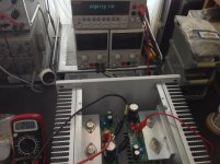
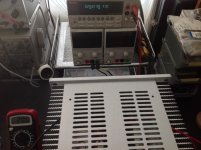
My bad, I forgot that I tested the boards with an external bias voltage for 20V.
Your pots are in separate in a bag with the setting at the midpoint...
Your pots are in separate in a bag with the setting at the midpoint...
Err, sorry, I didn't get that last one...
At the end, is the bias adjusted with your (much greater than mine) skills and top equipment... or should we in fact check voltages with our voltmeters for mere mortals... and possibly dare to alter your initial adjustment?
Sorry for being slow tonight (mean even slower than usual 🙂
Claude
At the end, is the bias adjusted with your (much greater than mine) skills and top equipment... or should we in fact check voltages with our voltmeters for mere mortals... and possibly dare to alter your initial adjustment?
Sorry for being slow tonight (mean even slower than usual 🙂
Claude
I am sure that with 36 VDC Meanwell the DC voltage at VFET Source shall be 20 VDC as building guide and documentation indicates.
I am thinking of Nelson setting the bias on "your" output board, with "your" pots , then desoldering them to put in "your" bag 😛
..or should we in fact check voltages with our voltmeters for mere mortals..
@ Claude G
Yes, we need check voltages.
Start with trimmer position in the middle, then adjust to 20V,
after 1hour warm of the Vfet amp adjust one more time if needed.
My was easy and quickly stable. Read Mr. Pass article..
Look at excellent 6L6 guide 🙂 Sony Vfet (P, 2021) - diyAudio Guides
Attachments
- Home
- Amplifiers
- Pass Labs
- DIY Sony VFET pt 1