@ClaudeG nice write up. I would add that after you get the case dry fit perfectly you mark the corners somehow so it goes back the way it was when you do the final assembly. Don’t ask me how I know. . .
I learned a technique many years ago when I made ultrasonic transducers for fetal heart monitors. When I need a third or fourth hand I line up the joint, put a small drop of flux on it and then touch the joint with a fresh blob on the tip of the iron. Works great for me, and pardon me if everyone know this.
I learned a technique many years ago when I made ultrasonic transducers for fetal heart monitors. When I need a third or fourth hand I line up the joint, put a small drop of flux on it and then touch the joint with a fresh blob on the tip of the iron. Works great for me, and pardon me if everyone know this.
As I said: DHL eCommerce sucks!
Whoa! It happened! I received my parts kit! I can't believe it's really here... DHL eCommerce still says that the parcel is on the go 😱
I'd suggest to think again about what shipping service to use for the next kits / lottery.
 Good news!
Good point Billyk, and also the order to mount everything back...
mbrennwa, glad you finaly got it!
mbrennwa, glad you finaly got it!
Some news from N. 22 🙂
...
0) Check the C1 caps on the OS boards have the right orientation and R7 is on the filter board. I am lucky, no early boards...
1) The LS terminals are great quality, no doubt on that. The crimping bits less so in my case, but no drama of course. Not a problem to crimp if you have the right equipment (crimping tool with a "rack"), but a nightmare re tolerances. I spent over 1h to adjust every single bit with blades and screwdrivers and pliers to make sure they fit correctly. They were all way too tight, very difficult to fit and would have been impossible to undo in situ (well taking into account the small recess). I would advise you try all the parts before assembling and make sure they fit tight while being able with moderate forces (and no pliers) to undo them.
2) The kit is easy to solder, really well done, very straight forward to assemble all boards. There is one bit that can be a bit of a hassle though: the SMPS power connector wires. I am used to SMD & Co, but this is a different problem. OK, not a majour one, but sadly not the 5 min job I expected to get the 4 wires on the connector. It is not easy to get the cables in the right position (and no, adding some solder before hand on the small connector legs as done usualy didn't help at all in my case, on the contrary). And of course, the more you progress, the more space gets cramped, so plan beforehand. I am lucky to have a thin soldering iron with a 0.3mm tip and a remote power station...
3) You may want to use tall metal stand offs. For the input filter anyway, as that helps a lot future doing and undoing (you just let them at the floor, easy location) plus it gives way more margin re cable length. Further, it allows also to move the filter back or further way (see poor pix), and that helps cabling and also possibly future upgrades re additional filters with an additional board, who knows, if Mark releases it...
...
Claude
The spade lug terminals were tight fitting but nothing that small pliers can't fix. I used angled fine tip pliers small enough to lift in the female lug contacts and open the fitting slightly. Word has it that ZenMod likes the crimps 😀 But in my case, I don't have professional crimping tools and have always soldered the wires - oh and it should be noted that the stripped hookup wiring JUST FITS in the crimp hole, like not even a strand extra would fit in so when you strip the insulation off, do not distort all the strands with some pliers.
For all the boards I soldered lug tabs which makes soldering easier (if any changes had to be made) than bare wire through a solder hole.
"Look Ma! No mangled looking crimps!"

Wire length was not an issue as I had the output stage board center of the heatsink and the front end boards closer to the rear panel.

we all know that soldering is outa fashion ......... and that regular Greedy Boy is all about lightning fast swapping of boards and wires ........

Well, at least I spent a few hours with a friend around the build. Oh, and while at it after a few hours I used him for blind testing absolute polarity - something that puzzled me since Papa mentioned it. I thought I wouldn't be sensitive to that (whereas I am to negative H2), but it turns out I am somewhat sensitive and with 14 right guesses out of 14, well... bugger, another hassle for my plans as I now need to take care of that aswell LOL
But back to the build. Super-BQ, yours look great! And yes I am still pondering lug tabs vs connectors with screws. I love the former and dislike the latter, but I will as for most things I am learning here... open my mind again and decide. BTW, if using lug tabs, I would rotate 180° the FE board you have at the bottom of your pix, as that would make soldering and desoldering much easier, albeit in your case with the FE moved forward perhaps not much more.
Still thinking, as I want also max flexibility re filter board, in case another filter steps in 🙂
Have a nice night
Claude
Last edited:
I am utterly confused by this paragraph. I am thinking of mounting the FE just like Super BQ, rotated 180° To the original recommendation. Why do think returning to the originally un-rotated orientation makes them easier to solder? Also, rotating is not possible with the OE as is, the FE card will only get two bolts aligned.…BTW, if using lug tabs, I would rotate 180° the FE board you have at the bottom of your pix, as that would make soldering and desoldering much easier, albeit in your case with the FE moved forward perhaps not much more…
Claude
Also, both his FE (due to the rotation) and the Output stage are moved BACKWARDS, not forward. So I am again confused.
Can you elaborate a bit your thoughts on rotation in terms of soldering? Again, really confused here.
Err... as said, my baseline is the std recommandation, so I am considering a 180° rotation from what is in the guide (and as said only 2 screws to hold FE). If your from there on you turn around another 180°, you end up in the same as in the guide... don't see the point...
Anyway, I am not yet done, I am also pondering many other things re cabling, including connections (screws terminals, lugs or else). I want to be able to swap easily filter boards and FE boards, and while at it play around PS caps... so some thinking ongoing.
But that's just me, not what is recommanded! And I am likely to have to change the cable connections slightly from the schematic for that. Still on it: it will take some time, I am busy in my real life lol!
I don't know exactly what Super BQ did, I am refering to the "only shared reference": Jim's / 6L6 guide... who knows, perhaps we are saying the same, perhaps also Super BQ did similar. By the look of it (posted pix), not exactly IMHO, so let's wait perhaps that I build mine to see feasability and if I am not just fooling myself. Plus you will have (poor) pix: might be easier than my poor wording 🙂
Sorry for the confusion
Claude
Oh, perhaps I understand better your comments... please note that the boards as originaly intended aren't rotated the same way for R and L, things aren't symmetrical.
I want it symmetrical - only for access reasons, mainly just unbolting the top panel and being to play, nothing to do with the sound of course. Downside are yes, indeed, only 2 bolts instead of 4... well, not a prob in my eyes.
Need more time to elaborate
Claude
I want it symmetrical - only for access reasons, mainly just unbolting the top panel and being to play, nothing to do with the sound of course. Downside are yes, indeed, only 2 bolts instead of 4... well, not a prob in my eyes.
Need more time to elaborate
Claude
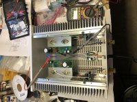
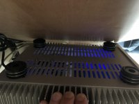
Well I finally got to flip the switch...and no explosions
#101 appears to be alive
Just set the bias at 20V
Going to let it simmer for an hour with the lid on before rechecking.
Hope to be hearing some music from it this evening.
#101 appears to be alive
Just set the bias at 20V
Going to let it simmer for an hour with the lid on before rechecking.
Hope to be hearing some music from it this evening.
Attachments

I didn’t give the amp a chance to cool off after I rechecked the bias...just pulled the amps I was using off the cabinet first and then ran downstairs for the VFET still hot and hooked it right up in less than a minute.
Having the benefit of everything else being warmed up in the system for a good hour or so is nice.
Always so much fun to have a new toy...and this one has me with a big smile on my face. 😀
I am currently still getting used to the Tannoy DMT II I chased down not that long ago. I wanted to see why Papa and many others seem to rely on dual concentric speakers as a “reference”...of course, they’re not a pair of the pricy Golds. Still, they appear to have a reputation as a speaker that will reveal more about recordings and equipment.
I have had a lot of fun with open baffle experiments recently...unfortunately, I recently had a problem with a woofer.
Once I get things sorted out with the OB I hope to spend some time comparing the VFET to the ACA and F2J amps I’ve built. My understanding is I can’t run the F2J with the Tannoys because its a current source amp and won’t work properly with the crossovers.
I think its interesting that many people have commented that the VFET amp is so quiet...it is. However, both the ACA and the F2J have the same dead silent quality to them.
That has always been very important to me when using speakers that have higher sensitivity.
The tube amps I was just using are Quicksilver Horn Monos which were designed to be used with high sensitivity horn loudspeakers. They are also dead silent between tracks.
My first impression of switching from the tube amps to the VFET amp so quickly (literally in the middle of an album) was the rock solid authority that the bass developed in addition to a sense of more overall clarity and detail.
I was listening to Bjork’s Vespertine album...which has a beautiful landscape of sounds created with all sorts of instruments and samples. It’s fun when I occasionally identify the source of a particular sample I hadn’t previously.
I’m looking forward to spending a lot more time listening...before the next build 😉
Thank you to everyone who brought this project to life.
Attachments
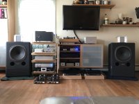
I bet the pairing with these high efficiency speakers is excellent.
By the way, from a distance this looks like a nice analog rig (cleaning machine, peripheral ring, at least two arms on the table)... 😎
By the way, from a distance this looks like a nice analog rig (cleaning machine, peripheral ring, at least two arms on the table)... 😎
Hi Pierre
Yes I am enjoying the VFET amp with these speakers very much right now.
These Tannoys do come up a bit light at the bottom end. I have a Jamo sub I have been using below 75 Hz.
I am less compelled to have the sub running with the VFET driving the Tannoys.
It does depend on the type of music.
I listen with to a lot of Downtempo electronic music during the afternoon that I like the sub on for.
In the morning I listen to mostly classical and there is no reason for it to be on. Evenings are mainly Jazz but also Blues. I can go either way, again depending on the particular material.
The analog rig was quite a project. Here is a link to a thread where I documented a lot of the work.
VPI resto-mod...a tale of bastardizing my HW19
I actually have a couple of other turntable projects that are in a holding pattern. I want to try my hand at a full on “reference” Lenco idler.
I do feel I need to devote some more time to another phono amp first.
I’ve been obsessed with amps and speakers lately.
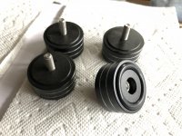
On the subject of amps...since this thread is about building the VFET amp...has anyone mentioned to make sure you put the feet on the bottom plate before you attach it to the bottom of the amp assembly and bolt the PS Filter board to it?
I felt foolish that I missed this detail in the excitement of trying to finally get to fire the amp up.
It’s pretty much impossible to get your hands or a tool inside the chassis to hold any nuts you might need to in order to tighten the feet hardware.
My situation was compounded by the fact that I was trying to use some machined aluminum feet I had on hand.
I wanted to shift the feet out as far as possible while still using the last vent slot at each corner of the bottom panel to mount them.
They obviously ended up hitting the mounting screws for the bottom panel.
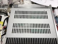
I ended up using some stainless flat head hex drive hardware I had in my bins that I was able to countersink the holes for so it was flush with the panel surface. I did the same for the top plate because I liked how it looked. Then I was able to shift the feet out over the panel mounting screws.
On the rear panel I used some button cap stainless hex socket hardware.
I wrestled with the wire issue as most others did.
I think if I had realized before hand that the 6” or 8” wire segments were not the exact requirements for both channels I would have been more careful to cut only the shorter length needed for the closer channel connections first and that would have left more wire for the longer runs.
I tried this strategy with the binding post wiring. However, I still came up short with the orange wire.
In the end I just went into my bins and used some standard copper 18 gauge green and red wire I had on hand.
I had plenty, and was able to run them under the boards where there was more room and also twist them like the input wiring.
I had some mil-spec wire that was like the provided wire, but in the wrong colors and gauge.
This way I don’t have to worry about my music sounding overly “tinny” 😉
Yes I am enjoying the VFET amp with these speakers very much right now.
These Tannoys do come up a bit light at the bottom end. I have a Jamo sub I have been using below 75 Hz.
I am less compelled to have the sub running with the VFET driving the Tannoys.
It does depend on the type of music.
I listen with to a lot of Downtempo electronic music during the afternoon that I like the sub on for.
In the morning I listen to mostly classical and there is no reason for it to be on. Evenings are mainly Jazz but also Blues. I can go either way, again depending on the particular material.
The analog rig was quite a project. Here is a link to a thread where I documented a lot of the work.
VPI resto-mod...a tale of bastardizing my HW19
I actually have a couple of other turntable projects that are in a holding pattern. I want to try my hand at a full on “reference” Lenco idler.
I do feel I need to devote some more time to another phono amp first.
I’ve been obsessed with amps and speakers lately.
On the subject of amps...since this thread is about building the VFET amp...has anyone mentioned to make sure you put the feet on the bottom plate before you attach it to the bottom of the amp assembly and bolt the PS Filter board to it?
I felt foolish that I missed this detail in the excitement of trying to finally get to fire the amp up.
It’s pretty much impossible to get your hands or a tool inside the chassis to hold any nuts you might need to in order to tighten the feet hardware.
My situation was compounded by the fact that I was trying to use some machined aluminum feet I had on hand.
I wanted to shift the feet out as far as possible while still using the last vent slot at each corner of the bottom panel to mount them.
They obviously ended up hitting the mounting screws for the bottom panel.
I ended up using some stainless flat head hex drive hardware I had in my bins that I was able to countersink the holes for so it was flush with the panel surface. I did the same for the top plate because I liked how it looked. Then I was able to shift the feet out over the panel mounting screws.
On the rear panel I used some button cap stainless hex socket hardware.
I wrestled with the wire issue as most others did.
I think if I had realized before hand that the 6” or 8” wire segments were not the exact requirements for both channels I would have been more careful to cut only the shorter length needed for the closer channel connections first and that would have left more wire for the longer runs.
I tried this strategy with the binding post wiring. However, I still came up short with the orange wire.
In the end I just went into my bins and used some standard copper 18 gauge green and red wire I had on hand.
I had plenty, and was able to run them under the boards where there was more room and also twist them like the input wiring.
I had some mil-spec wire that was like the provided wire, but in the wrong colors and gauge.
This way I don’t have to worry about my music sounding overly “tinny” 😉
Attachments
Well, I can say with great joy that #86 is up and making amazing music!
Thanks so much to Mr. Pass, Jim (6L6), Jason, and everyone at the DIY store! As I have said before, you give us the gift of music in our homes, and I can think of very few things that are more important.
My situation was particularly difficult in terms of shipping logistics, and Jason was incredibly kind and patient with me and my country's laws. Thanks, truly a big debt of gratitude from me towards all of you.
As mentioned before by others, since some of us are so late to the building process, our contributions are going to be fewer and less important.
For what is worth, here is a couple of things I did a little different, may be useful to others or the rebuttal of my changes by others would be useful for further readers.


Now, I finished late yesterday, but couldn't refrain from having a go with my main system. WOW! Just at first turn on, the complete lack of "hiss" from the tweeters is really obvious and a big difference from my previous amp. After having a listen (still in break in), I concur with others that the bass is much fuller with this amp compared to my other. I was wondering if this could be due to the higher presence of 2nd harmonics? A 40Hz pitch will have a higher-than-usual 80hz harmonic, which would still sound very much like a "bass enhancement". Or maybe this amp is just much better than my previous one, and that's it! 🙂
Today, listening a bit more carefully, it's a beautiful sound! It's really "silky" but that smoothness and subtlety does not take away any of the details. In fact, I can hear more detail than with my previous amp. But that level of detail does not equal "bright" or "harsh" sound. It is quite a remarkable thing.
Also, the soundstage is much deeper and wider than what we were used to. You can hear music coming from a deeper space, and not from the speakers.
Due to this more "round" sound, I can listen at lower levels of sound and still be filled with the music much more intensely. Obviously, I need to run my preamp at a much higher volume to achieve similar volume levels, as expected. This may not be a bad thing, since previously I was running my PRE at 15 or 20% of its volume, now I am listening at 75%, so it's also less intrusive, which can be a good thing.
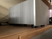
So, I will burn it in a bit more before really sitting down with a good glass of wine and enjoy music with my wife. In the meantime, here it is, still temporarily on the top shelf, as soon as everything is finalized, it will replace the amp below.
Thanks again so much for this amazing piece of equipment that renders art like nothing we have heard in our home. It feels like we upgraded our speakers to much better ones, just by changing the amp.

Best wishes to all the other builders,
Rafa.
PS. As a final advice, take photos of your work!!! I actually photographed mine for posting here after considering it "done", and the photo showed two poor solders on the ground of the Output Board of the left channel which now have been reflowed and fixed.
Thanks so much to Mr. Pass, Jim (6L6), Jason, and everyone at the DIY store! As I have said before, you give us the gift of music in our homes, and I can think of very few things that are more important.
My situation was particularly difficult in terms of shipping logistics, and Jason was incredibly kind and patient with me and my country's laws. Thanks, truly a big debt of gratitude from me towards all of you.
As mentioned before by others, since some of us are so late to the building process, our contributions are going to be fewer and less important.
For what is worth, here is a couple of things I did a little different, may be useful to others or the rebuttal of my changes by others would be useful for further readers.
- I did a "dress rehearsal" of the different parts inside the chassis just to better comprehend the complexity of the build. It is perfectly well documented in the guide by 6L6, so there is very little guesswork (if any at all?). Still, I think it's a good idea to do a dry run and see what happens. During that process I decided to, as others, rotate the FE cards 180° and move them straight back to the rear panel.
- I decided to use metal standoffs for the input filter. With so many tests and flipping over of the chassis to finish the work, I really wanted to avoid having to deal with bottom screws as much as possible.
- I really battled with the idea of having either the front panel or the rear panel with torsion applied with the screws from rails being a tad smaller than the heatsinks. The common agreement here is: "move them back, the front panel can take it". I didn't want that at all. I decided to put some epoxy-glued washers on the back panel and moved the rails to be flush with the front panel. I think that is a much more secure fit.
- This next advice is perhaps not needed, but since there is so much to do, at one point I just followed 6L6s guide and cramped two blue connectors to the switch cables of the filter. Unfortunately, my kit had 4 blue ones for the larger speaker posts, and two smaller red ones for the switch. I realized this too late and had to cut those two and replace them. So, basic advice here, inspect your components and think things through, do not blindly copy the guide, as colors may vary. This is not a critique to the guide, this was all on me and a stupid mistake, just a heads up for others.
- Seeing some of the cable work here is obvious that there is a lot of talent amongst the builders here... but it is only after you have tried to do it yourself that you realize just how much work went into those perfect squared cablings we see here posted. My deepest respect for the fellow builders. Mine is nowhere near as neat, but I am happy with the result:
Now, I finished late yesterday, but couldn't refrain from having a go with my main system. WOW! Just at first turn on, the complete lack of "hiss" from the tweeters is really obvious and a big difference from my previous amp. After having a listen (still in break in), I concur with others that the bass is much fuller with this amp compared to my other. I was wondering if this could be due to the higher presence of 2nd harmonics? A 40Hz pitch will have a higher-than-usual 80hz harmonic, which would still sound very much like a "bass enhancement". Or maybe this amp is just much better than my previous one, and that's it! 🙂
Today, listening a bit more carefully, it's a beautiful sound! It's really "silky" but that smoothness and subtlety does not take away any of the details. In fact, I can hear more detail than with my previous amp. But that level of detail does not equal "bright" or "harsh" sound. It is quite a remarkable thing.
Also, the soundstage is much deeper and wider than what we were used to. You can hear music coming from a deeper space, and not from the speakers.
Due to this more "round" sound, I can listen at lower levels of sound and still be filled with the music much more intensely. Obviously, I need to run my preamp at a much higher volume to achieve similar volume levels, as expected. This may not be a bad thing, since previously I was running my PRE at 15 or 20% of its volume, now I am listening at 75%, so it's also less intrusive, which can be a good thing.
So, I will burn it in a bit more before really sitting down with a good glass of wine and enjoy music with my wife. In the meantime, here it is, still temporarily on the top shelf, as soon as everything is finalized, it will replace the amp below.
Thanks again so much for this amazing piece of equipment that renders art like nothing we have heard in our home. It feels like we upgraded our speakers to much better ones, just by changing the amp.
Best wishes to all the other builders,
Rafa.
PS. As a final advice, take photos of your work!!! I actually photographed mine for posting here after considering it "done", and the photo showed two poor solders on the ground of the Output Board of the left channel which now have been reflowed and fixed.
Last edited:
- Home
- Amplifiers
- Pass Labs
- DIY Sony VFET Builders thread