It’s been some time now with my VFET beauty. Not quite sure how to describe it. I don’t have very efficient speakers at 86db (NHT 2.5i) I do plan on bi-amping but not currently though. Even so, I do get enough volume for a very satisfying listing session.
I was using a Korg B1 and a Parasound HCA 1000a. Putting the VFET in place was a revelation that’s for sure. I let it run for a few days while I built an ACP+. Placed the ACP+In there and OMG is all I could say. I can honestly say that I’ve never heard my recording sound like this, never. The level of detail is incredible, voices, strings, bass, oh man the bass. Sorry I’m not much good with descriptive prose. I can tell you I’ve been up late every night going from song to song to song. . .
Thank you again to all involved, I’m so fortunate to be able to have something like this.

..Do you see any downside doing what I did with the resistor?
On another note, having just soldered the bits today, it seems to me you have very different parts re Zener and other surrounding bits (not the big resistors obviously) - Is it me?
It's just acrobatic for 3W power resistor 😉
For long therm reliability horizontal position is better, less mechanical stress on soldering joint imho.
I think about one easy tip : twist some piece of the copper wires together with two channels zeners leads or 1R5 resistors
so will be temporaly physical extension for voltage adjustement with big crocodiles etc.
After all is OK , put this extension wires out of the circuits..🙂
Oh yes precision matched resistors pairs for FE and OS signal path..it's a hobby pleasure.
Thanks ClaudeG for kind words 😀 Have a nice evening
It’s been some time now with my VFET beauty. Not quite sure how to describe it. I don’t have very efficient speakers at 86db (NHT 2.5i) I do plan on bi-amping but not currently though. Even so, I do get enough volume for a very satisfying listing session.
I was using a Korg B1 and a Parasound HCA 1000a. Putting the VFET in place was a revelation that’s for sure. I let it run for a few days while I built an ACP+. Placed the ACP+In there and OMG is all I could say. I can honestly say that I’ve never heard my recording sound like this, never. The level of detail is incredible, voices, strings, bass, oh man the bass. Sorry I’m not much good with descriptive prose. I can tell you I’ve been up late every night going from song to song to song. . .
Thank you again to all involved, I’m so fortunate to be able to have something like this.
View attachment 957102
View attachment 957103
I agree with billyk. I have it powering some speakers that are not a "good match" both in terms of impedance and sensitivity, but it's still very enjoyable at modest listening levels actually. Really better than expected. Gain is quite low so I am anxious to get my ACP+ in front of it.
Thanks Soundhappy 🙂
Guess the joints given resistor's weight and thermal expansion should survive the stress... the other ideas are also good for the future in a way or another - thing is I may need some permanent "docks" for some tries or add-ons... thinking of combining various ideas, good talking to you, need sparring partners LOL
Enjoy your evening very much too and thanks again for your kind reply
Claude
It’s been some time now with my VFET beauty. Not quite sure how to describe it. I don’t have very efficient speakers at 86db (NHT 2.5i)...
Both ACP and PVFET are still to be built for me and I do have a 2.5i also currently bi-amped which I'm loving. That is probably why I'm procrastinating...


Has anyone played with bypassing C2 on the FE boards?
I wanted initialy to build the VFET EXACTLY as intented by Papa, to have a baseline, and then only think about any mod re FE, PS filtering... but again only once I have a baseline and comparing before and after (reversible) mods, if any. that's what I always do.
Usualy this is quite easy as the boards can be removed in my builds, or there is access underneath for add-ons etc. Now, I realise that taking the FE board in and out to add a cap isn't going to be very effective and may be time consuming, so perhaps it is wiser to make one of the mods sadly beforehand without knowing its sonic impact. I was thinking about bypassing C2 on the FE board, the 1000uF electrolytic cap in the signal path with something quite safe re resonnance and side effects, in form of a smallish 1uF Wima MKS I have on hand, something that could fit under the board while probably making sense in terms of value and tech. It is quite a similar idea to what Papa did on the 10000uF cap on the OS board - I understand it might have possibly negligeable effects, but well, why not asking?
Has anyone tried this or similar? I mean really comparing before and after, not just fitting it straight away, to evaluate any possible sonic impact of a similar bypass in this FE section?
Many thanks and enjoy music
Claude
Hallo Claude,
though I don't have experience with the situation in the DIY VFET, whenever I tried an MKS or other Polyester film cap, I have not been satisfied. Never liked the sound; often I thought of it somewhat edgy or unrefined.
My tips for bypass caps are WIMA MKP4 or MKP10, though I realize that these are quite a bit bigger.
The other caps I tend to like are MKC (polycarbonate) caps. For example, ROE MKC1860 don't take up much space.
Or Zen Mod's favourite, the Philips MKC ... 🙂
Best regards,
Claas
Hi Class,
Yes, I am with you, I also prefer PPP, but sadly no space under the board for those (well, could still find some big stand-offs). Or I could chose the easy way: extension legs coming out of the board for tries, but that would mean a few cm away from between the legs, so additional R and I would like to avoid that. It needs some more thinking on my side I guess...
MKS & Co can sometimes be a blessing to balance things, but indeed not neutral as I would like. The positive is from our exchange you convinced me even more on how important it was to stick to my beloved process: having first the VFET built as intented, and then evaluate each mod one by one. Would be pity to degrade the Papa sound with my silly mods without even knowing it because I didn't compare before and after. And with MKS there is indeed to big a risk as you kindly reminded me of. Plus I might have other plans re FE anyway...
Many thanks for your message, helps thinking clear at night / avoiding silly thoughts
MFG
Claude
I one feels a burning urge to experiment with capacitors in the signal path, best is to look at a different model of electrolytic before playing around with small value film caps.
Elna RFS series 470 uF, 50V, Silmic II would be my first recommendation. Currently available at Mouser. Give it at least 24 hours of run-in before making a decision.
Nichicon KZ series 470 uF, 50V. or KW, FG, KA series are in the next category, all rated for audio.
Don't worry about 470 uF or even 440 uF compared to 1000 uF; all values result in a LF roll-off below 1 Hz, at which point it doesn't matter anymore.
If you want to read some truly obsessive accounts of bypass caps in the signal path, check out the FirstWatt F3 thread (commercial version of Zen v9). Original design by N. Pass used a 15,000 in parallel with two other values and types. Many pages of capacitor discussion. Read for entertainment purposes.
Thanks for your kind reply.
Well, not a big fan of Silmic II so far, but that's from another build. Yep, could change the lytics, but adding quality caps often gives the same result if not better. IME Having said all that, I may want to address something that doesn't exist first hand. So I will leave it here for the moment, or make provision for it somehow. I had indeed recently a build where adding bypass made 0 difference (or nearly so). And yep, thanks, familar indeed with Fc and cap value, opens somewhat the door.
I will have a read at this F3 thread, interesting, thanks again!
Claude
Hallo Claude,
though I don't have experience with the situation in the DIY VFET, whenever I tried an MKS or other Polyester film cap, I have not been satiefied. Never liked the sound; often I thought of it somewhat edgy or unrefined.
My tips for bypass caps are WIMA MKP4 or MKP10, though I realize that this are quite a bit bigger.
The other caps I tend to like are MKC (polycarbonate) caps. For example, ROE MKC1860 don't take up much space.
Or Zen Mod's favourite, the Philips MKC ... 🙂
Best regards,
Claas
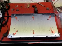
I’m just starting work on mounting the OS brackets to the heatsinks.
Just using the guide to try and sort out hardware...mimicking what I see in the pics.
I saw the brackets were already in place on the heatsinks prior to the OS mounting...so I started the same way.
First thing that popped into my mind was previous posts in the thread regarding rear panel alignment...and also suggestions of “dry fitting” the whole chassis together before actually installing and wiring everything into it.
I’m not sure how necessary preassembly is...honestly, the tolerances are what they are and any misalignment will have to be compensated for by shimmying this or that or adding a washer etc.
However, while pondering assembly I thought to myself “Should I use Loctite on the chassis brackets and hardware holding the faceplate or any other panels?”
The reason being is that there are no lock washers and the constant heat cycling may cause hardware to come loose.
So...anyone using Loctite anywhere?
Attachments
use split washers
Loctite (blue) is overkill there, it can make your life complicated later, from whatever reason
you can use nail polish, it's having enough Loctiteness for this purpose
Loctite (blue) is overkill there, it can make your life complicated later, from whatever reason
you can use nail polish, it's having enough Loctiteness for this purpose
Some people do report crackling sounds... maybe not Loctite, but actually split washers?
Edit: ZM beat me to it, for once that I had a good idea! 😛
Edit: ZM beat me to it, for once that I had a good idea! 😛
Thanks ZM and Rafa
My first impression was that the screws were a bit short for lock washers...but I pulled out my small hardware bin and found some that work fine.
My first impression was that the screws were a bit short for lock washers...but I pulled out my small hardware bin and found some that work fine.
I’m just starting work on mounting the OS brackets to the heatsinks.
Just using the guide to try and sort out hardware...mimicking what I see in the pics.
I saw the brackets were already in place on the heatsinks prior to the OS mounting...so I started the same way.
First thing that popped into my mind was previous posts in the thread regarding rear panel alignment...and also suggestions of “dry fitting” the whole chassis together before actually installing and wiring everything into it.
I’m not sure how necessary preassembly is...honestly, the tolerances are what they are and any misalignment will have to be compensated for by shimmying this or that or adding a washer etc.
However, while pondering assembly I thought to myself “Should I use Loctite on the chassis brackets and hardware holding the faceplate or any other panels?”
The reason being is that there are no lock washers and the constant heat cycling may cause hardware to come loose.
So...anyone using Loctite anywhere?
I've found 1 rail in my build was slightly concave and all end tabs aren't touching to front or back panel. I used a hammer to bang the tabs so they would close up a 2 or 3 mm gap, then screw on.
As ZenMan says, no need for Loctite... things could go fugly later on.
The amp doesn't really get that hot.
I would just say mount those rails even with the back of the heatsink where the thin rear panel will be mounted or it's likely to bow when tightened down. It's not a problem with the front panel because it's so thick, a gap there is ok. I thought about Loctite for a second, but ended up not using it myself.
- Home
- Amplifiers
- Pass Labs
- DIY Sony VFET Builders thread