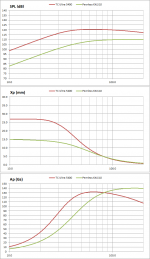
Since peak acceleration is proportional to Xp(peak excursion) x (frequency)^2, the largest accelerations generally occur at the top end of the bass range (80hz – 100Hz), not at the lower frequencies even though Xp is much larger there. When using smaller diameter, shorter stroke woofers, Xp can be just as high as for a large long throw woofer like the Ultra5400 in this range. Example plot compares SPL, Xp, and Gs for the Ultra5400 and the more pedestrian XXLS10. (Ultra 5400 driven with 1500W, the XXLS10 200W) Both would need an accelerometer capable of handling ~150Gs.I´ve got some samples of the +-70g types also, which are more suited to most drivers. +-250g is rather the range for one of those extreme longthrow beasts like TC Sounds Ultra5400.
Thanks for the heads-up on the potential for high noise floor, did not recall that comment. What I had remembered was a comment about a 400hz LP filter built in to some of the sensors, but these particular chips do not have such a filter.… ADXL chips are rather too noisy due to all the electronics involved ..
Attachments
Hi all,
Well after chasing down a problem with squareness that turned out to be a sacrificial fence that took on moisture (don't use melamine boys and girls, no matter what they tell you), it seems my donated BB had been sitting against a Michigan garage too long and has a slight warp. 🙁
I thought that once over here (laying flat etc.) the issue would go away but hasn't. I think that leaves me no choice other than to use butt joinery, given that any other cut would be too risky trying to run through absolutely correctly. My previous experience with this is that they will correct themselves during glue up and major clamping.
Unless someone has a better idea, this is unfortunately the route I'll take, and use a roundover bit to make them look acceptable.
I do have all the pieces cut, baffles routed. braces are next as I decided against the dowels. Why? looking at the provided plans again, it seems the build I linked to upthread, did indeed have the braces to spec, and I not going to deviate (except for overall box configuration).
All for today on "Adventures in woodworking'...
Hi wreckingball,
I'm in the finishing stages of remodeling a bathroom, and-to save money-I'm reusing the plywood from a 60+ year old vanity and a 3'x4'x8' build-in closet... 🙂
Your approach sounds fine, use screws where you have to for clamping/holding (watch out for them when routing). It's a good idea to stick to the provided plans, at least that way you have a reference.
Good luck,
Regards,
Hi,
I did those g-calaculations too ... but restricted to <200Hz iIrc so that the figures wouldn´t grow too much .... it´s about subwoofers anyway so one can assume a working range <<100Hz.
As one increases the bandwidth the required g-range increases also, which on the other hand may then result in issues with the resolution of the sensor, resp. noise.
What imho seems passed unnoticed is that the quality of the sensor, its dynamic range, linearity, resolution and noise performance dictates the limits of the fed-back system in first place.
Accelerations sensors can have noise figures in the low µg/sqr(Hz) range down to a few Hz (similar to the 1/f noise curve of OPAmps) while the ADXL sensors specify noise in the mg/sqr(Hz) range .... almost a factor of 10³ higher!
Besides it seems that these sensors are obsolete parts already ... single-axis accelerometers with analog outputs are getting rare. 😡
jauu
Calvin
All true and worth keeping in mind for the future.As one increases the bandwidth the required g-range increases also, which on the other hand may then result in issues with the resolution of the sensor, resp. noise.
What imho seems passed unnoticed is that the quality of the sensor, its dynamic range, linearity, resolution and noise performance dictates the limits of the fed-back system in first place.
Accelerations sensors can have noise figures...
But for today, we have speakers with more than 10% harmonic distortion at low frequencies and horrible "group delay". Also, I don't know how you'd parameterize resonances that add 10 dB to the FR - should that be called 30% loudness distortion?
My point is that the shortcomings of speakers are very big and the shortcomings of all the types of sensors used for MF are pretty small. Not to be ignored, of course.
(Some sensor shortcomings do matter a lot such as dynamic range.)
Ben
But for today, we have speakers with more than 10% harmonic distortion at low frequencies and horrible "group delay".
Really? It's time to look at some actual data before making clearly incorrect statements.
Group delay first - I showed you group delay sims coming in at around 8 ms IIRC. That's hardly "horrible" as it's completely inaudible at the low frequencies that it occurs at. And further, "group delay" is not a euphemism for some mysterious and evil phenomenon, it's literally phase related real delay at certain frequencies, so you don't have to keep putting the term in quotes.
Distortion next. You do realize distortion is directly related to how loud you play the speakers, right? Depending on the volume knob any given speaker can play with WAY more or WAY less than 10 percent distortion.
Since you refuse to believe that there are decent modern speakers that are more than capable of playing very loud with very low distortion, here's actual measured Klippel data.
http://circuitcellar.com/wp-content...kasonTBench_BCSpeakerReprintedwPermission.pdf
This is just a normal $400 18 inch driver, not a super state of the art miracle.
Note how symmetrical all the measured curves are - Bl, Kms, Le.
You are always complaining that a starched fabric spider and a rubber half roll surround is hardly a perfect spring BUT LOOK AT THAT KMS CURVE - it's almost a perfect spring, not perfectly symmetrical but not far off.
This driver is limited by Bl at 10.7 mm (82 percent, which corresponds to 10 percent distortion). That means that the driver can move 10.7 mm one way before hitting 10 percent distortion. That's equivalent displacement to about 10 of your antique AR-1 woofers.
Here's actual commentary from the write up on this "picture perfect" driver.
Klippel analysis for the B&C 18TBW100-8 produced
the Bl(X), Kms(X) and Bl and Kms symmetry range
curves shown in Figures 5–8. The Bl(X) curve for the
18TBW100 is very broad and extremely symmetrical
(see Figure 5). It is what a loudspeaker engineer would
call “picture perfect” since both the Bl curve and its
accompanying offset curve are almost exactly overlaid.
Looking at the Bl symmetry plot, the offset curve is
mostly invisible since it tracks at the 0 offset level out to
10 mm and only slightly below (coil-in rearward offset)
beyond that (see Figure 6). Figure 7 and Figure 8
depict the Kms(X) and Kms symmetry range curves for
the 18TBW100. The Kms(X) curve is as symmetrical as
possible in both directions, with a trivial 0.75-mm offset,
which is further confirmed by the Kms symmetry curve,
almost a straight line at the zero rest position tracking
again at a non-significant 0.75-mm coil-out (forward)
offset. Great job, guys!
Displacement-limiting numbers calculated by the
Klippel analyzer for the 18TBW100 were XBl @ 82% (Bl
decreasing to 82% of its maximum value) 10.7 mm,
and for XC @ 70% (compliance decreasing to 70% of its
maximum value) was 11.5 mm, which means that for
this B&C 18" woofer, the Bl is the most limiting factor
for a prescribed distortion level of 10%, but for either
element, the contribution is several millimeters beyond
the physical Xmax. If I use the subwoofer criteria for
20% distortion, the numbers are XBl >13.3 mm and XC
>13.3 mm.
Figure 9 shows the inductance curve L(X) for the B&C
pro sound subwoofer. Inductance will typically increase in
the rear direction from the zero rest position as the voice
coil covers more pole area unless the driver incorporates
a shorting ring. Since the 18TBW100 does incorporate an
aluminum demodulation ring (shorting ring) in the motor
assembly, there is only an extremely minor change in
inductance, about 0.15 mH, from Xmax in to Xmax out.
- Status
- Not open for further replies.