... one more a little abstract question. As stylus is not tangential to both the groove wall can this be corrected by electronic delay circuit ?
It's a good question. My feeling is a worm drive with comparator to work like the Indian 230 V stabilisers would be good ( Volt Smart, I have one ) . The humble LM324 or 339 would be OK, they use the 324. Make the arm able to rotate to protect records if the servo fails. It will also allow variomatrix recordings to play without the servos working too hard. Don't assume low mass is best.
My work with some calculations suggests a 16.5 inch Schroeder clone would be profitable. My tentetive suggestions are 409.5 mm spindle to center. 9.5mm overhang and 12.9 degrees. If I read my notes correctly. There are a lot. I think 30g mass for the Denon DL110 I might try would be OK.
I suspect the best answer to the question about time delay is if the playback can be most like the cutting that is the best you can do.
few questions.
1) in pivoted tonearm as pivot is fixed and due to offset angle the tonearm is pulled towards the center. Which forces act upon linear tonearm so that it moves across the record ?
2) theoretically with regards to tracking error how much difference is between linear and pivoted tonearm ?
Regards
its not the tonearm that causes the stylus to move across the record its the spiral groove cut into the record.
there is no tracking error on a linear tonearm as it follows the same path as a cutting head.
linear tonearms are not popular as they are very difficult to implement properly and as such are expensive to make. pivoted tonearms are more popular due to being relatively simple to make.
a properly designed linear tonearm is miles apart from a pivoted in terms of sound quality. once you have heard a linear tonearm there is no going back. this is why DIY air bearing linear tonearms are popular. even using exotic materials will cost you £1k in parts but you will have the equivalent of a £3k+ arm. building one from angle alloy will cost a looot less but its very pain staking precise work and can be fiddly to set up. there are many different ways to implement a linear tonearm and each have their strengths and weaknesses.
Hi,
Could you define "properly designed" please ?
TIA, 😉
a properly designed linear tonearm is miles apart from a pivoted in terms of sound quality.
Could you define "properly designed" please ?
TIA, 😉
Thanks Gentlemen.
I did had a Technic Linear Tracker. It sounded good. I had posted somewhere a rough drawing of stylus profile (Conical) touching opposite groove walls for tangential and a pivoted design. How ever it was difficult to assess how much difference (on paper) in degrees with regards to contact points the stylus makes to both the groove wall. Will try with friends CAD software. I also presume how long and short the modulations are on groove walls will affect the difference. High frequency modulation will obviously have significant benefit but long modulations less so.
Since linear tonearm requires absolutely frictionless movement, A dual pivot linear tonearm would be good. Isn't it ? A simple drawing posted here #925 .
... If the turntable platter is with strobe facets. why can't reflection from it be used to calculate the distance needed and move the tonearm tangentially ? or a single point reflector so with each rotation the tonearm can be moved appropriately.
Hiten. You are right. I have the JVC L3-E version of a similar turntable. It has the nasty habit of sounding very good. The most important thing is to have some movement. A unipivot would be excellent with a worm drive.
Some interesting trends. A 7 inch arm is to show the trend, it would be difficult to engineer for no advantage. The results are. Length. Spindle to pivot. Overhang. Headshell angle. Null points. Distortion max and average. Please suggest better outcomes. The more interesting is SME 9 inch. It is not the high distortion device some claim. The sound must be simply it is more from the old school before the Ortofon patent finished. I didn't show the 10 inch as I didn't have all the data. It is almost exactly like the 9 inch from the data I had. The big surprise is the 16.5 inch arm is just as critical for offset. About 4 % distortion if zero,
7inch. 177.8 ( 155.8 ) 22mm OH 30.3 deg 63.1/116.3 mm D m/a = 1.1/0.6
9inch SME M2. 232.2 ( 214.4) 17.8mm OH 23.63 deg 66.4/120.1 mm D m/a = 0.7/0.4
12inch SME M2. 308.8 ( 295.6) 13.2mm OH 17.62 deg 66.4/120.1 mm D m/a = 0.5/0.3
Linn Ekos 9 inch 229 ( 211 ) 18.0mm OH 24.0 deg 65.7/120.7 mm D m/a = 0.7/0.4
16.5 inch 419.1 (409.7) 9.4mm OH 12.8 deg 64.0/121.7 mm D m/a = 0.4/0.2
500mm 500 ( 492 ) 8.0mm OH 10.8 deg 64.7/122.7 mm D m/a = 0.3/0.2
Last edited:
... If the turntable platter is with strobe facets. why can't reflection from it be used to calculate the distance needed and move the tonearm tangentially ? or a single point reflector so with each rotation the tonearm can be moved appropriately.
When I was 2 years old in 1958 I had a little bus made in Germany. It would never fall off of the table. It had two gravity switches. That's all you need and a timed drive. You could time the worm drive to 3 minutes ( a 78 ) then have limit switches to complete the job. I might be possible using a 600 RPM motor on AC even. That can be switched using an MOC3020 ( 100 mA ). I tried that for a few days and had no problem. Maybe someone would like to calculate the ideal motor and worm drive ? 250 RPM is another common type. a 1.8 stepper will do 60RPM @ 50 Hz. That takes us into steppers themselves if the complexity is OK.
The JVC is with Colleen who has an A level in domestic science and no weighing scales! That is also very typical of hi fi people to not have the test gear. I took the little metal arm off, it weighs plenty. I will take a proper measurement when I remember. The JVC boys knew what they were doing. I am now loking for another for my old boss Julian Mason. It's small enough that he might actually use it with his A&R A60 I rebuilt. The generic stylus I bought for Colleen is excellent.
Thank you sir.
A cheap flatbed scanner scans at 2400 dots per inch with stepper motor. One only has to feed the stepper motor voltage with reference to platter rotation. Stepper motor would move the arm across precisely. Will that work at all ? OR Would that be too easy a solution ? A sensor can detect the platter rotation as mentioned earlier if one wants all this assembly to be isolated.
Regards.
I think it will. Have speeds you need for 33.33/45/78 and fast track select. For your first tests use an average time to play records. For simple results a unipivot. It is important to get something working before being fussy about details. If it works well it could be refind to go faster and be stopped by a limit switch. The limit switch could be given rules to work with which I am sure will not be as simple as you might think. The arm might be best to be longer than is typical. This allows for the swing at the end runout ( so as not to upset the stylus ). If running the fast version that would be less of a problem. You could make a runout detector that lifts the arm. If so the simple solution is possible. That detector could be the next step to building the fast version. A Schroeder type bearing could be used and wood tube. I suspect a unipivot more practical when starting out.
One idea that came to me was a Schroeder style bearing on a very tight long cord. Maybe with a powerful damped spring at the other end to the motor. The cord moves on a stepper drive. The cord might be something unusual. I doubt that anything that allows movement would have good sound.
One idea that came to me was a Schroeder style bearing on a very tight long cord. Maybe with a powerful damped spring at the other end to the motor. The cord moves on a stepper drive. The cord might be something unusual. I doubt that anything that allows movement would have good sound.
interesting thoughts about a DIY Schroeder tonearm...
guys: As Nigel points out, simple detectors can be used. I think something like this was done on the Rabco linear arms. They used a belt, and an arm that had a pivot that was very limited in the lateral plane.
BTW Nigel: wow. That JVC seems like an unsung hero. and the same motor and platter were used in the more upscale JVC TT81, etc. If found, could be a real steal 🙂
oops, had a thought (I seem to have so few...): There certainly can be a way to create a pretty decent "linear tracker" passively. The unfortunate thing is that it all adds weight and complexity. SO how could we do something that is completely passive? Perhaps a hybrid, such as a DIY air bearing tonearm, that moves a pivot along its path. A typical unipivot could then be used. The arm is moved laterally as per a typical LT, but the unipivot would allow for minor corrections. If done correctly the mass of the arm itself could be greatly reduced (because it would be much shorter). Because the stylus would be acted upon by the friction of the groove, it would be "pulled forward. The the LT part would keep it moving laterally.
One detail: If an approach as I suggest above is used, the moving pivot must be underling, below the air bearing surface.
I think Schroeder himself made a very short arm that did something like this, although along a curved path (the arm base basically rotated IIRC).
Nanook that's absolutely right. I was talking to Paul Stewart Ex of JVC today about something else ( a mutual friend and tone arm length, he dislikes the Jelco 12 inch whilst liking the 9 inch ). Paul said the next model up from JVC TT81 is the same as the JVC cutting lathes. Paul was the one who thought to use the redundant plant at Mobile Alabama from CD4. As far as I know the Technics was a JVC design and patents. VHS also. L3-E and L5-E were nearly 100 % TT 71. The 5 even had a MC pick up option. As said before JVC X-1 was a game changer. It was for CD4 as was the Mobile cutting lathe. Although CD4 was a white elephant the double frequency range wasn't. As I also said the standard JVC Z-1 was nothing special. The X-1 was Shibata tipped Z-1. I told Paul off for not taking the fight to Linn in the 1980's. He said it was impossible.
I too would be upset to see this thread go over to linear tracking devices. They do have a place in the Schroeder story. I would love to see someone take this up. I have a mountain of work so must resist. Like power steering it needs to be helped along.
I think the gentleman who made this clone arm could consider a 16.5 inch version. A friend said a fishing rod shaft in carbon fibre would be cheap and far better than typical hi fi versions. It might start to have enough mass at that length. 18 g would be ideal.
a couple of points re: JVC DD tables, and comment on carbon fibre safety issues
Doing a little research on the Olde Interweb resulted in some great iinformation regarding what each of the better JVC direct drive tables is and other models that share its mechanicals. Check out: the vintage knob LE-5 and others.
Sounds like a very good documentation project. This could be a great resource if it could be done with Mr. Schroeder's assistance.
Regarding the modifying of any thing carbon fibre: I'll do my usual warning and strongly suggest that any working with any hardened carbon fibre products should be aware of the health risks involved (including cutting or modifying any carbon fibre products). Only do so at your own risk, and follow any recommendations regarding respirators/filters and airflow in the workplace. The fine particles can make their way into your airway and create health concerns. If unsure, have an archery supplier cut the shaft to the desired length.
Regarding mass, be careful what you wish for. I don't think anything with a 12" shaft of real mass of 14 grams should occur. Based on that, and an almost 45% increase in effective length (and therefore total length from one end of the arm shaft to the other) should result in an arm of mass of approximately 18.7 grams if the same aluminum shafts that I use in the 219 tonearm are used
Nanook that's absolutely right. I was talking to Paul Stewart Ex of JVC today about something else ( a mutual friend and tone arm length, he dislikes the Jelco 12 inch whilst liking the 9 inch ). Paul said the next model up from JVC TT81 is the same as the JVC cutting lathes. Paul was the one who thought to use the redundant plant at Mobile Alabama from CD4. As far as I know the Technics was a JVC design and patents. VHS also. L3-E and L5-E were nearly 100 % TT 71. The 5 even had a MC pick up option. As said before JVC X-1 was a game changer. It was for CD4 as was the Mobile cutting lathe. Although CD4 was a white elephant the double frequency range wasn't. As I also said the standard JVC Z-1 was nothing special. The X-1 was Shibata tipped Z-1. I told Paul off for not taking the fight to Linn in the 1980's. He said it was impossible.
Doing a little research on the Olde Interweb resulted in some great iinformation regarding what each of the better JVC direct drive tables is and other models that share its mechanicals. Check out: the vintage knob LE-5 and others.
I too would be upset to see this thread go over to linear tracking devices. They do have a place in the Schroeder story. I would love to see someone take this up. I have a mountain of work so must resist. Like power steering it needs to be helped along.
Sounds like a very good documentation project. This could be a great resource if it could be done with Mr. Schroeder's assistance.
I think the gentleman who made this clone arm could consider a 16.5 inch version. A friend said a fishing rod shaft in carbon fibre would be cheap and far better than typical hi fi versions. It might start to have enough mass at that length. 18 g would be ideal.
Regarding the modifying of any thing carbon fibre: I'll do my usual warning and strongly suggest that any working with any hardened carbon fibre products should be aware of the health risks involved (including cutting or modifying any carbon fibre products). Only do so at your own risk, and follow any recommendations regarding respirators/filters and airflow in the workplace. The fine particles can make their way into your airway and create health concerns. If unsure, have an archery supplier cut the shaft to the desired length.
Regarding mass, be careful what you wish for. I don't think anything with a 12" shaft of real mass of 14 grams should occur. Based on that, and an almost 45% increase in effective length (and therefore total length from one end of the arm shaft to the other) should result in an arm of mass of approximately 18.7 grams if the same aluminum shafts that I use in the 219 tonearm are used
Returning to subject. 10 mm OD 8 mm ID carbon fibre of the usual type is 45.6 g / metre and 24.7 g/M if of the 1 mm wall thickness. Cost is peanuts. Looking at 400 mm we get 19 g or 10 g more or less. The lighter could be foam filled ( soft ). This allows plenty of scope for even the dainty pick ups.
Lets say 27g all up for the worse case. Denon DL 110. Fo = 1/ 2Pi root ( 27 x 8.5 u ) = 1000/6.3 root ( 230 ) 1000/96 = 10.4 Hz ( 1000 is 10-6 rooted and inverted ). I could live with that when a 16.5 inch arm. Real life resonance will be different. All the same it gives a clue to do the maths. 90% of the time it will be as good as you need. Also simple mass and how it really works is different. That isn't really important. Start somewhere and see where it goes. A test record is useful. Looking at all the daft records we can buy why not a DIY Audio test disc as cheap as possible ( not me ) ? 5 Hz to 100 Hz of 20 seconds with a voice saying what is what. It could be cut with low distortion to do set up checks. Perhaps,5,6,7,8,9,10,11,12,13,14,15,16,17,18,19,20, 25,30,35,40,45,50,55,60,65,70,75,80,85,90,95,100,250,500.5,1K ( longer ) 2K22, 5K, 10K,15K,20K,25K. The other side 5,6,7,8,9,10,11,12,13,14,15,16,17,18,19,20, horizontal plus other things.
I must say if the gentleman who made this arm presented the forum with this test record at perhaps less than $20 I would really admire him. I can admire someones skills to make a beautiful thing. I had a friend who could fake old masters in art. He always used modern paints to be sure no one tried to pass them off. I thought of asking him to do a painting to show the number 1.618 ( Phi ) in the style of Mondrian. Wish I had as it seems not to be an abuse of an idea.
1.2 x Phi x Phi is Pi to a very good approximation ( I was told a solution linking the two exists in some type of logarithm, I never found it, logically it should exist ). Phi is ( 1+ root [5] )/2 ). Pi x Pi x Pi = 31 to a good approximation. Phi is the most real numer I know of 0.618 1.618 2.618 are the shortened reciprical and also squares where +/- 1 offers the solution. Phi power 10 is as best we can say 123. This to me suggests 10 is a good counting system. If I remember Phi on base 12 is not so interesting. 12 is promoted as a better number. This might ignore root 5 as an important number. Hope this stimulates someone. Phi is a useful number when understanding filters and how they work on the ear. Better than the lazy use of x squared. PHi can be approximated by any two numbers as long as they are not both 0. This says to me 0 is a concept and not a number. The interesting thing is the speed to arrive at a solution is not greatly different regardless of numbers chosen. It was so long ago that I can not remember what negative numbers do and I am old enough not to work it out. 1 and 1000 are nice. 1001,2001,3002,5003,8005,13008,21013,34021,55034 = 1.6177 this early into the sequence. Notice how the classic numbers run like a zipper up the sides of the big number and one can infer the next.
A little theory the space fans have is Pi in base 12 is a rational number. It isn't
3.184809493B9186645
Now Pi to base Phi???? Too old to bother. It should link somewhere. What I have learnt is real numbers are not. Pi and Phi are real. That follows Stew's tag line nicely. Real maths is slightly odd. People say infinity is hard to think of. Not really as the alternative is harder. Anyway infinity is a concept as it hasn't happened yet and never will. Like zero we would find life impossible without these really abstract numbers. If you think about it life without irrational numbers would be rather dangerous. The square root of -1 is my favourite number. The older I get the more I suspect it to be real.
Anyone in UK right now Radio 3 is giving the quality I remember from the past. Stunning. 10.22 AM. I am using a truely analogue tuner the Quad FM3. Off to work now.
something else quite interesting...
and something else quite interesting:
𝛑²≅℮²+ (i/℮)²+ϕ² (apparently there exists a Pythagorean relationship between ϕ, e, and 𝛑
I'll let the math geeks remember or derive it all them selves, but IIRC from a course I took a long time ago (Mathematical Methods in the Physical Sciences) Doing an expansion of e results in a series of "odd" and "even" expressions. The odd order results were fraction representations of sin (rational numbers), while the even order results were imaginary multiples of a rational number and represented cosines.It has been a long time...so I could be wrong, but my initial statement regarding the relationship between ϕ, e, and 𝛑 holds true.
1.2 x Phi x Phi is Pi to a very good approximation
and something else quite interesting:
𝛑²≅℮²+ (i/℮)²+ϕ² (apparently there exists a Pythagorean relationship between ϕ, e, and 𝛑
I'll let the math geeks remember or derive it all them selves, but IIRC from a course I took a long time ago (Mathematical Methods in the Physical Sciences) Doing an expansion of e results in a series of "odd" and "even" expressions. The odd order results were fraction representations of sin (rational numbers), while the even order results were imaginary multiples of a rational number and represented cosines.It has been a long time...so I could be wrong, but my initial statement regarding the relationship between ϕ, e, and 𝛑 holds true.
16 inch Schroder toneram :
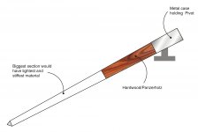
Since we are incerasing length, to decrease total mass we can use three different stiff material of varying density, to make it comparatively lighter. Triangle being stronger shape we can taper the whole assembly from pivot to headshell. This will reduce mass, give damping at various frequency levels and tapering would stabilize the longer tonearm. Three intersection of tonearm can be varied to suit the cartridge compliance and sound preference. A rough illustration attached.
Regards.
Attachments
Hiten I love that idea. I am trying to think of easy geometry for getting the headshell angle right. Some A4 paper and trig tables seems one way. My tables 1878. Have a screw in long finger lift to see the angle. That is replaced by a short one for use. The Schroeder fixing is the logical solution to simplify the task. Hiten, I bet Rose Wood is a local product and other beautiful woods?
If it isn't too boring. The Phi + e = Pi triangle ( Pi is c ,hypotenuse) is < 0.7% wrong. Also the sum squares ( a, b ) are almost exactly 10. I think from memory the angles are 89 and 31 the anti-tan of e/Phi is 59.23 deg. If it was 60 the whole world would be much more boring. Instictively 60 would be what you might exspect from two geopmetric irrationals. Mad numbers rule your world. This is why linearity is a slightly false concept. Best we have, so best keep with it.
Pi/root 2 = 2.22 to 0.065%. I think I have used that in my electrical engineering days somewhere. Root 2 also with the addition of 1 is interesting ( see tan ) . ( Root {2} + 1 ) squared = 5.828427. 5.828427-3 = 2 root 2 as it would . Which is also e x e/ Phi x Phi to 0.51%
The most accurate coincidence is Phi = ( 7/5 ) Pi/e You can take Pi to be 355/113. e to be 2721/1001 and Phi as 843/521 ( powers of Phi not usual Fibonacci numbers ) or 987/610 in the usual series.
The result 1.6180182897073 against a calculated real Phi at 1.6180339887499. Less than 0.001% error. 7/5 Pi nearly = 4.4. Thus 4.4/e = Phi to 0.04% . The thing to note is 5 very often pops up and will 2. These are the divisions of 10. It is hard to say if we fitted these observations arround 5 x 2 fingers. Mostly likely we did. All the same geometry is not a slave to numbers.
Someone said 8 has changed over time but e hasn't. That's silly. 8 fingers is 8 fingers and that's the reference point.
I only speak a little Spanish. I watched about 4 hours of Euclid on Cuban TV. Because it was maths the Spanish was easier to understand. The teacher took many paths and was trying to get the students to find a route they could understand. I was transfixed and had not seen 50% + of the proofs. The guy choose to teach from their rain forest. I sort of understood that, but less than the maths or the Spanish.

If effective length and pivot to spindle distance is fixed we can make fixed offset angle marking on the headshell itself which would give tentative cartridge alignment position.I am trying to think of easy geometry for getting the headshell angle right.
Yes sir. Teak, Sheesham and rosewood are popular here. In that order. Cheaper woods are Babul, Sal and Deodar. Don't know properties of cheaper wood. We had used Sal wood for small shutters and they bend during changing weather.Hiten, I bet Rose Wood is a local product and other beautiful woods?
Regards.
- Home
- Source & Line
- Analogue Source
- DIY Schroeder Tonearm?