Nelson Pass said:Anyway, I have decided that I need a more robust line level
stage to drive my F4 followers, so I might as well kill two birds
with one stone.
😎
hehe
time for toobz.............talkin' about serious preamp

Would it be possible to make a tristate buffer as input in a preamp so you could avoid source selection relays?
Chances are Nelson, That you've been finalizing the design recently??? May I suggest a "Light Speed" type Volume control of sorts???
Please, 😀 😀 😀
Please, 😀 😀 😀
Nelson Pass said:Anyway, I have decided that I need a more robust line level
stage to drive my F4 followers, so I might as well kill two birds
with one stone.
😎
Mr. Pass, I would like to wish for a JFET preamp that can handle balanced and unbalanced inputs/output but doesn't suffer in gain (ROBUST) when you switch to unbalanced. And make it output bal/unbal signals at the same time without losing gain on either one. And make that a balanced single-ended design🙂 like the BOSOZ. And make that... please!

I am with Blues, all the way🙂
Steen🙂
Mr. Pass, any chance that the F4 is a higher powered Lovoltech thing? 😎my F4 followers
Steen🙂
I would be interested to see what type of headphone amp Mr. Pass
would come up with. 🙂 Doesn't have to be a full blown write up,
maybe just a schematic, like he did with the Chip Amps.
would come up with. 🙂 Doesn't have to be a full blown write up,
maybe just a schematic, like he did with the Chip Amps.
cviller said:Would it be possible to make a tristate buffer as input in a preamp so you could avoid source selection relays?
Possible, but likely to color the sound more than relays.
any chance that the F4 is a higher powered Lovoltech thing?
It's not, but it does use JFETs on the input.
moe29 said:I would be interested to see what type of headphone amp Mr. Pass would come up with. 🙂 Doesn't have to be a full blown write up, maybe just a schematic, like he did with the Chip Amps.
It's my observation that headphones don't usually need voltage
gain, and in those cases a simple single-ended buffer is probably
the best circuit. When I have time, I'll try to draw a quick
schematic.
😎
moe29 said:I would be interested to see what type of headphone amp Mr. Pass would come up with.
Moe,
buy yourself the best AKG, then ask NP for what he has already given.

(I'll even donate you a couple of dual JFETs for a JF1)
Nelson Pass said:
Already done, since it meets my needs as well.
😎
Are you going to share this design Mr. Pass? Something similar will surely be Cloud 9 for all of us.

Blues said:Are you going to share this design Mr. Pass? Something similar will surely be Cloud 9 for all of us.
Well yes, I guess that's why I bring it up as the next project.
😎
Originally posted by moe29
I would be interested to see what type of headphone amp Mr. Pass would come up with. Doesn't have to be a full blown write up, maybe just a schematic, like he did with the Chip Amps.
Moe,
I've built a couple of headphone amps out of the Aleph circuit, but sadly the exact schematic died in a hard drive crash a couple of years ago before i got around to sharing it here. It shouldn't be too hard for me to do a little probing around to get the resistor values, so bear with me and I'll see what I can do for you.
Cheers, Terry
Nelson Pass said:Anyway, I have decided that I need a more robust line level
stage to drive my F4 followers, so I might as well kill two birds
with one stone.
😎
Sad
I wanted to see Papa's integrated amp, and wanted to produce PCB for some secret pocket money invisible to my wife.

Happy
I will have Papa's new thing soon.
🙂
Recipe for heaphone amp:
1 Gate stopper, 221 Ohm, nominal value
1 Source resistor for bias, 50 Ohm, nominal value--note that it needs to be able to dissipate something on the order of 12W continuously
1 power MOSFET, I used a Motorola part that was pretty similar to the IRF610 (MTP7N20E? something like that)
1 DC blocking cap for the output, this will need to be an electrolytic--the actual value will depend on the impedance of your headphones--I think I used a 1000uF 35V Panasonic FC
1 film bypass for the DC blocking cap, I used WIMAs...look in your junkbox
Add +-24V rails, heatsinks to taste, and stir until thoroughly mixed.
Note that the circuit is quite capable of cooking itself--you won't need an oven.
I splurged and used Caddocks for the biasing resistors. They've got a nice resistor that looks like a miniature TO-247...takes something like 20-30W. I mounted it on the same heatsink as the MOSFET.
The above circuit biases up at .5A. That's more than enough for multiple pairs of Grados or any other current hungry headphones you might have lying around. If you want to decrease the bias current, increase the value of the bias resistor. Decrease it enough and you can start thinking in terms of the blue Panasonic 3W resistors, even if you have to series or parallel them.
The thing is so simple you can point-to-point it in no time. Because I'm anal about such things, I made circuit boards to keep it tidy.
Nuthin' to it.
Sounds mahvelous, by the way.
Also keeps your pizza hot.
Grey
Nelson Pass said:
Well yes, I guess that's why I bring it up as the next project.
😎
I'm already
 , Mr. 😎!
GRollins said:Recipe for heaphone amp:
1 Gate stopper, 221 Ohm, nominal value
1 Source resistor for bias, 50 Ohm, nominal value--note that it needs to be able to dissipate something on the order of 12W continuously
1 power MOSFET, I used a Motorola part that was pretty similar to the IRF610 (MTP7N20E? something like that)
1 DC blocking cap for the output, this will need to be an electrolytic--the actual value will depend on the impedance of your headphones--I think I used a 1000uF 35V Panasonic FC
1 film bypass for the DC blocking cap, I used WIMAs...look in your junkbox
Add +-24V rails, heatsinks to taste, and stir until thoroughly mixed.
Note that the circuit is quite capable of cooking itself--you won't need an oven.
I splurged and used Caddocks for the biasing resistors. They've got a nice resistor that looks like a miniature TO-247...takes something like 20-30W. I mounted it on the same heatsink as the MOSFET.
The above circuit biases up at .5A. That's more than enough for multiple pairs of Grados or any other current hungry headphones you might have lying around. If you want to decrease the bias current, increase the value of the bias resistor. Decrease it enough and you can start thinking in terms of the blue Panasonic 3W resistors, even if you have to series or parallel them.
The thing is so simple you can point-to-point it in no time. Because I'm anal about such things, I made circuit boards to keep it tidy.
Nuthin' to it.
Sounds mahvelous, by the way.
Also keeps your pizza hot.
Grey
Great!
By thw way, it seems that the input side is missing . . . ?
Left out two resistors, which is what I get for trying to remember a circuit when I haven't had any sleep:
Drop one from the MOSFET's Gate to ground. You can use a pot here, if you need a place to control the volume. Something like 10k to 22.1k will do just peachy.
Drop another from the output to ground in order to drain the charge off the backside of the cap at turn-on. Not critical in value. 1k, 10k...whatever comes to hand when you reach into the junkbox.
Input side missing? Nope, just the one ground reference resistor/pot. There's only one transistor in the whole thing. It's a Source follower, Signal goes in at the Gate, and out via the Source.
Simple. By design.
Scads of people have built these things, with the usual variations in components. Yes, you can add a Zener or two to the input if you want to safeguard against static (I didn't). If you really want to get crazy, you can replace the biasing resistor with a current source, but you'll double your parts count for little, if any sonic gain. You might even find that it sounds worse. I'm content with a resistor.
It's dead silent, flat as a 10 year-old's chest, and non-inverting. What's not to like?
Being a card-carrying member of the Lily-Guilder's Society, I pulled together a power supply sufficient for a small amplifier. Why? Just to use up some junk box stuff.
Grey
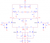
Pretty close to the well-known Szekeres headphone amp:
http://headwize.com/projects/showfile.php?file=szeke1_prj.htm
If you have an output cap anyway, is there any need for the +/- supply?
I found with my 300-ohm Sennheisers, I needed a bit of gain, even from a CD player.
It would be nice to put these Lovoltechs to good use.
http://headwize.com/projects/showfile.php?file=szeke1_prj.htm
If you have an output cap anyway, is there any need for the +/- supply?
I found with my 300-ohm Sennheisers, I needed a bit of gain, even from a CD player.
It would be nice to put these Lovoltechs to good use.
- Home
- Amplifiers
- Pass Labs
- DIY progress report