How about this for a DIY project:
High gain opamp based preamp for low output MC cartridges. | Page 91 | Audiokarma Home Audio Stereo Discussion Forums
MC or MM, 46-72dB gain, warp (elliptic) filter, multiple parallel input AD797s, SMPS, line stage, optional headphone amp. Ultra low measured distortion, including many tone tests. Very High overload margin over the entire audio band, typical RIAA compliance to +/-25mdB 20Hz-20kHz, better than +/-100mdB worst case. DC coupled. Tested, measured, quality boards. >100 built of the phono/line stages.
Tested, measured, quality boards.
Were any measurements of common-mode noise made? I'd be interested to see them if so.
Below is a link to a drop box with the info of an earlier version. The salient schematic is included.Hi. Is it possible for you to post the schematic?
Dropbox -Phono Stage - Simplify your life
Were any measurements of common-mode noise made? I'd be interested to see them if so.
Common mode noise? Please explain what you mean.
You're using an SMPSU, they always are common-mode noise generators. Call it ultrasonic leakage current if you prefer - that current has to go somewhere. I take it you're taking signal ground to safety earth at some point?
There is no DC short between safety (mains) ground and the SMPS ground. There is an optional capacitive connection to the chassis (safety ground) at the input and output section grounds of the SMPS. The amplifier is isolated from chassis and relies on the grounds of the driven amp to provide signal ground.
There is a ground post available on the chassis.
Noise etc. measurements are made with the preamp in circuit, driving the output power amps using an RME ADI-2 PRO FS and REW.
There is also an additional local ground referenced LC filter added at the output of the SMPS to reduce HF switching noise.
There is a ground post available on the chassis.
Noise etc. measurements are made with the preamp in circuit, driving the output power amps using an RME ADI-2 PRO FS and REW.
There is also an additional local ground referenced LC filter added at the output of the SMPS to reduce HF switching noise.
Last edited:
So effectively your implementation is class 2 (i.e. double insulated) ? In which case noise currents divide between the (optional) capacitor to safety ground and the downstream component (which may or may not have a DC connection to safety ground) via the ICs.
Do you have measurements of how much of the noise current flows down the ICs ?
Do you have measurements of how much of the noise current flows down the ICs ?
Not as such. I do have measurements of the total noise at the preamp output, as digitized by the RME box. The measurements were made with a sample rate of 192kHz and 384kHz, and I posted the 192kHz result, which shows very low level SMPS spurs near the measurement band edge.
What is your concern?
Testing using many tone signals does not indicate any significant SINAD degradation due to out of band IM products folding back into the audio band, if that is your concern.
High gain opamp based preamp for low output MC cartridges. | Page 5 | Audiokarma Home Audio Stereo Discussion Forums
post #64. shows a possibly relevant measurement.
High gain opamp based preamp for low output MC cartridges. | Page 72 | Audiokarma Home Audio Stereo Discussion Forums
Post #1427 might be interesting.
Last edited:
I do have measurements of the total noise at the preamp output, as digitized by the RME box. The measurements were made with a sample rate of 192kHz and 384kHz, and I posted the 192kHz result, which shows very low level SMPS spurs near the measurement band edge.
Those would be normal mode measurements, not common-mode ones right? So the amount of CM noise which converts to normal mode (and therefore shows up on your plot) would be a function of the measurement kit's CMRR plus the kinds of cables you used (transfer impedance being a crucial parameter).
Is the measurement kit comparable to a typical audio preamp would you say?
Do you happen to know the switching frequency of your SMPSU?
My concern is how much ultrasonic garbage sent along the shields of your ICs is being left to the downstream component to deal with.
Fine. But that certainly doesn't seem to be a problem in the system in which the preamp is being used and measured.
Also, the design is supply source agnostic. Use batteries, use linear. Use a pair of separate identical 15v SMPS wall warts with their appropriate terminals in series, use the local output filter- builders (myself included) have done all of the above- the audible and measurable results all seem to be essentially identical.
Refer to the plot identified in post#52 for SMPS switching spurs. The 384KHz sampling rate test did not show additional relevant detail.
Last edited:
But that certainly doesn't seem to be a problem in the system in which the preamp is being used and measured.
Pleased to hear that and thanks for addressing my concerns. I hope your project gains significant traction here amongst the vinyl-philes.
The many tone test pointed to in post #52 is with the entire system in place- the phono stage, input cabling and attenuator, exterior passive volume control driving the line stage, power amps active, but speakers disconnected. Signal taken from "record" output- which is post input line buffer and at the top of the passive attenuator relay/resistor stack, driving the RME input- which is very similar to a normal preamp with a 9k input impedance and c. 1m interconnect cabling.
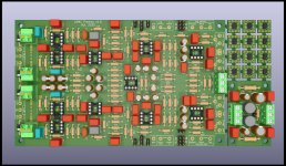
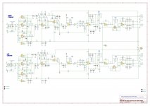
Schematic of preamp and layout.Hi. Is it possible for you to post the schematic?
Headphone amp is separate.
Attachments
Pleased to hear that and thanks for addressing my concerns. I hope your project gains significant traction here amongst the vinyl-philes.
Is it worth actually posting the project as a thread?
I'm only a sometime visitor to DIY Audio, and I'm uncertain as to the perceived value of such an effort.


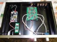
I built one of Wyn's preamps about a year ago and am starting to build another, this one with an added headphone amp board and warp filter board. My preamp was on display at the 2019 BAF.
Subjective performance observations to add to Wyn's measurement data and responses here are that it is extremely quiet in operation, even compared to about 9-10 other preamps I have (Threshold, Audible Illusions, Spectral, Adcom GFP750, Mark Levinson No. 38, Apt, etc.). Sound is very articulate, clean and neutral.
I use the preamp for both MC phono and other line sources, and have connected it to each of my amps - Conrad Johnson, Adcom GFA585LE, Mark Levinson, Sony, tube mono blocks I built, Forte, Adcom GFA5500, Nakamichi PA7AII. Sound is excellent with each, without reserve.
My phono sources are an Oracle Delphi with a Soundsmith Zephyr MIMC, and a Micro Seiki BL-91 with a Benz Micro Ace L. C and R loading are adjustable by swapping each in sockets.
It seems clear to me that having a very skilled engineer and designer (he worked for Analog Devices as an op-amp designer) has resulted in a very fine performing preamp, and a great, affordable DIY project. I was even more pleased when he agreed to design the headphone circuit based on my input and the specs of my headphones.
Attachments
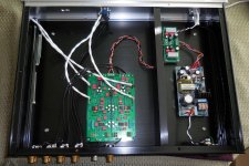
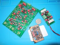
Here is another photo of the preamp board and the filter board for the SMPS. This my second build, which will include the headphone and warp filter circuits, as well as more line inputs, record out, and MC input. The smaller board is not associated with Wyn's preamp - it is an MC board for Apt Holman preamps.
Attachments
Here is another photo of the preamp board and the filter board for the SMPS. This my second build, which will include the headphone and warp filter circuits, as well as more line inputs, record out, and MC input. The smaller board is not associated with Wyn's preamp - it is an MC board for Apt Holman preamps.
Do you have links to more info, a BOM, a source for PCBs, etc?
- Home
- Source & Line
- Analogue Source
- DIY Phono Preamp Recommendation