geolemon said:
Yes, Tom Danley of ServoDrive owns quite literally all the patents to servo loudspeaker technology... I believe they are getting close in age to expiring in the next few years, though.
Dan Wiggins knows Tom Danley personally. 😉
ServoDrive makes the BassTech7, and ContraBass units, both of which use a single Pacific Scientific servo motor to drive a rotary-to-linear motion converter, which in turn drives a pair of 15" cones.
(I think actually I referenced the ContraBass and BassTech7 earlier in this thread... something joking about using servos due to their linear BL curve... I don't think anyone got it. 😀 )
There used to be a wonderful website with some DIY information - and a fantastic Tom Danley whitepaper on servo loudspeakers - called "The ContraBass Corner"... but sadly, it's gone.
Reward being offered for anyone who can find it, or at least the Tom Danley whitepaper.

Tom Danley also co-engineered a somewhat legendary woofer for Phoenix Gold - the Cyclone.
The Cyclone is the only rotary servo subwoofer to ever have been produced for the marketplace.
Hence, it's rare.
There's also an interesting little venture quietly existing out there called TWD Audio that exists out there... if you look, it's like a mini-ContraBass driver unit (12" cones rather than 15"), in a bandpass box, built for the car audio market.
I'm just speculating... but I find it suspicious that since no one can legally produce servo-powered loudspeakers without Tom Danley's (or ServoDrive's) approval, and since the company's name is TWD audio... just maybe possibly Tom Danley's middle name starts with a W? Little side venture? 😉
I honestly don't know, but it sure seems suspicious.
Here's a little information from my own web page you might be interested in:
A dissection of one of my Phoenix Gold Cyclone rotary subwoofers
My custom twin-motored DIY rotary SPL subwoofer project (still in progress)
About that TWD and Tom Danley's middle name, I think it does start with a W. I read that on a car audio forum, but I don't know if the guy who said it has merit. Tom I think is the one behind TWD, and theres a link to servodrive on the website (I think).
And that contrabass corner is gone because some of the parts became unavailable to the DIYers. I thought I read somewhere that they didn't want that information just out there anymore. Maybe it hurt business because people thought taht it could be done easily and cheaper? I don't really know. Maybe Mr. Danley can send you the info.
They were thinking of a DIY version of the TWD that they were supposed to email me about a couple years ago but I guess it never proceeded.
Hee hee, I was sure we'd get the story...
Didn't he also help design the Labhorn DIY bass horn?
For a while ServoDrive sold kits to DIY folks.
Another good reason to do it DIY: I doubt the patents would be an issue.
Linear motors can be servo too.
Didn't he also help design the Labhorn DIY bass horn?
For a while ServoDrive sold kits to DIY folks.
Another good reason to do it DIY: I doubt the patents would be an issue.
Linear motors can be servo too.
Hi Steven,
Don't make too much of my models--they're just my attempt at an apples-to-apples comparison of the two topologies, not my suggested blueprints for the final design. Both are fully scalable 🙂
Can you shed any more light on this for me? I guess I'm not familiar with the phenomenon you're talking about. AFAIK, since the two coils are actually two halves of the same coil (in series), they don't care about a variation of B over their surfaces, only what the sum is. If you or anyone else has something to teach me about this, I'm eager to learn.
Hey Chris,
You seem to have the skinny on Servodrive stuff--can you tell me the model number of the DC servo they use? I've got a truly wild servo-driven sub on my personal drawing board right now, and I'd love to know more about the specific motor they use for this app. so I can compare performance numbers.
Your curve definitely looks good. But it looks like all you have is about 1" linear throw one way. I thought the whole point of doing this was to get huge excursions like the Parthenon.
Don't make too much of my models--they're just my attempt at an apples-to-apples comparison of the two topologies, not my suggested blueprints for the final design. Both are fully scalable 🙂
Also, your total BL is very flat. But I still think you will have BL distortion. BL distortion comes from current (BLi). The current in either coil will see changing BL, and therefore may cause distortion, even though they are complimenting eachother.
Can you shed any more light on this for me? I guess I'm not familiar with the phenomenon you're talking about. AFAIK, since the two coils are actually two halves of the same coil (in series), they don't care about a variation of B over their surfaces, only what the sum is. If you or anyone else has something to teach me about this, I'm eager to learn.
Hey Chris,
You seem to have the skinny on Servodrive stuff--can you tell me the model number of the DC servo they use? I've got a truly wild servo-driven sub on my personal drawing board right now, and I'd love to know more about the specific motor they use for this app. so I can compare performance numbers.
OK, I had some time to doodle tonight. I decided to take another stab at a basic Parthenon motor layout while trying to adhere to a few rules, in order of importance:
(1) Use basic steel shapes for ease of fabrication and to increase the possibility of using low carbon steels.
(2) Increase magnet cross sectional area to increase flux.
(3) Use magnets that are less expensive (i.e., more common shapes).
(4) Keep it simple and elegant.
(5) Allow for DDD or standard design.
(6) Allow for a flexible design that makes it easy to use more or less gaps.
I wondered why you need multiple return paths if the pole piece is shared by all gaps. What I came up with is fairly simple. I calculate approximately 10 square inches of magnet cross section in the Adire Parthenon motor... this version has roughly 60 square inches, of whatever thickness is readily available. It would be trivial to increase that to 100+ square inches.
The basic element is a flat, square plate for each gap, with a hole bored in the center creating the return side of the gap. These plates are stacked at the desired distance, and then boxed in with more flat plates (presumably a bit thicker). The assembly could accomodate welding or bolted construction equally well. In fact, machining to provide for bolting would be very straightforward.
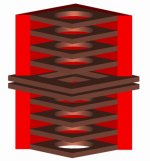
The version shown below is a four gap, DDD design using 2" x 2" square magnets sandwiched in the middle. I've rendered it with two of the outer plates removed so you can see the internals. The eight "gap plates" are all identical. All construction is simply cut from plate stock, holes bored, and if desired bolt holes drilled and tapped in appropriate areas (edges of gap plates...).
Any thoughts?
(1) Use basic steel shapes for ease of fabrication and to increase the possibility of using low carbon steels.
(2) Increase magnet cross sectional area to increase flux.
(3) Use magnets that are less expensive (i.e., more common shapes).
(4) Keep it simple and elegant.
(5) Allow for DDD or standard design.
(6) Allow for a flexible design that makes it easy to use more or less gaps.
I wondered why you need multiple return paths if the pole piece is shared by all gaps. What I came up with is fairly simple. I calculate approximately 10 square inches of magnet cross section in the Adire Parthenon motor... this version has roughly 60 square inches, of whatever thickness is readily available. It would be trivial to increase that to 100+ square inches.
The basic element is a flat, square plate for each gap, with a hole bored in the center creating the return side of the gap. These plates are stacked at the desired distance, and then boxed in with more flat plates (presumably a bit thicker). The assembly could accomodate welding or bolted construction equally well. In fact, machining to provide for bolting would be very straightforward.
The version shown below is a four gap, DDD design using 2" x 2" square magnets sandwiched in the middle. I've rendered it with two of the outer plates removed so you can see the internals. The eight "gap plates" are all identical. All construction is simply cut from plate stock, holes bored, and if desired bolt holes drilled and tapped in appropriate areas (edges of gap plates...).
Any thoughts?
Attachments
I think this would accomodate DDD or single sided XBL^2 equally well. Here is a cross sectional view of the pole piece and return if someone wants to check out the flux levels. Though it is a square motor design, it would probably model fairly well as an axisymmetric design... you'd have a bit more magnet surface area in the square design, but with slightly longer return paths in some areas. Pole gaps are obviously optional.
Attachments
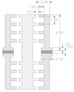
BTW, the model shown would weight somewhere North of 130 pounds without the pole piece. Not light... but then does it really need to be?
😀
😀
Hey RH,
Nice drawings! Food for thought.
One thing you should add to your list of rules, though, is to try always to place the cross-sectional minimum at the magnetic gaps.
With so much flux and inexpensive steel, we'll likely be driving the cross-sectional bottleneck of our return circuit to saturation. Ideally, you want that saturated portion to be the one closest to the voice coils (though many production motors compromise and saturate at the base of their poles).
As you guessed, it's not important to have entirely separate paths for the flux--that was just how it worked out with the square-steel-tubing approach. Cross section is what matters. Ideally, the area of the inner faces of the top plates should be perhaps 75% or less of the cross-sectional area of the rest of the return circuit--pole included. As I mentioned, many designers cut it much closer, but it's still a good thing to keep in mind.
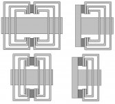
No nice renderings here, 😉 but here's another couple sketches in the penny-pinching structural tubing theme (rectangular sections this time instead of square).
This would broaden our magnet options considerably.
Edit: Added a further simplification--substituted a plate for the inner tubing section. this shortens the whole thing and saves cost and weight. However, depending on the magnet height, this may not allow enough depth in the single-ended approach.
This would broaden our magnet options considerably.
Edit: Added a further simplification--substituted a plate for the inner tubing section. this shortens the whole thing and saves cost and weight. However, depending on the magnet height, this may not allow enough depth in the single-ended approach.
Attachments
Hi all...
Lots of good ideas, but still a bit "cart before the horse...". A lot of these motor structures may work, depending upon the desired application of the driver. Might want to think about desired flux levels, moving masses, and desired stroke to start with, then think about designing the motor. Otherwise it's kind of a "shot in the dark" approach.
Also, keep in mind that using the DDD approach is patent infringement. Someone might want to contact HyperDynamics to start with, to make sure it's OK to use for this project. Yes, I am worried about IP, but that's because I do some work in the IP world (as a vendor).
Dan Wiggins
Adire Audio
Bill F. said:
Can you shed any more light on this for me? I guess I'm not familiar with the phenomenon you're talking about. AFAIK, since the two coils are actually two halves of the same coil (in series), they don't care about a variation of B over their surfaces, only what the sum is. If you or anyone else has something to teach me about this, I'm eager to learn.
Well I should mention it is only a theory loosly based on a similar idea. But because of the similarities I thought I would bring it up and hope that someone who really knows could agree, or call foul to the idea.
Dan, could you help us out here? I am very curious about this.
Lots of good ideas, but still a bit "cart before the horse...".
Guilty as charged.

Motor design so much fun, I easily get carried away.
Ok, I'll throw in my two cents on performance goals (just off the cuff--please don't hold me to this later
 ):
):As I mentioned before, I'm personally leaning toward a target Fs of 15Hz or higher, since this is a dipole application and we need all the efficiency we can muster around 20Hz. Qts could be as high as 1 (or higher!) for the same reason. Vas will be some enormous number that we hardly care about. (OB, ya know...)
I personally feel that 4-6" p-p would be plenty of excursion for this application, but I'm already preparing to cave when you maniacs out there scream for more. (I'll go like this: "Ok! Ok!" 😀 )
As for specific motor targets, In this application, I believe we are in no danger of designing a motor that's too strong. Our only no-no is designing one that's too expensive to build.
Therefor, I suggest that we pick a budget, pick a desired Xmax, and then design the motor for the maximum BL we we can squeeze out of it for that Xmax and price point. With the suspension and amount of moving mass we're looking at, I don't think we're in danger of building a motor so strong that Fs will be too high.
Also, keep in mind that using the DDD approach is patent infringement. Someone might want to contact HyperDynamics to start with, to make sure it's OK to use for this project. Yes, I am worried about IP, but that's because I do some work in the IP world (as a vendor).
Dan, you're one generous dude. 😎 If we decide to go with the DDD hybrid, I hope the chappies at HD can be convinced to send us some similar love.

PS. Would you be willing to address the question of the pros/cons of engineering a BL curve to compensate for linear/progressive suspension compliances?
I think and Fs of 15Hz is a good target. I was also thinking a highish Qtc for dipole application, though electronic equalization would be a practical alternative if a high Qtc causes other problems.
Here is my suggestion (pretty much parroting Bill here, as his thinking was right in line with my own)... keep the excursion "reasonable." I agree that 4" to 6" is a good range to aim for. Design the motor for the highest BL possible within the size and price constraints. The stronger the motor becomes, the larger (and heavier) the diaphram can become while maintaining the Fs goals, right? I'd personally rather have a driver with a 36" diaphram moving 6" p-p than one with an 18" diaphram moving 18" p-p.
So what is our collection of target goals thus far? 3" Xmax (one way linear), Qtc = 1, Fs = 15Hz. Can we nail anything else down at this point?
Dan... I'd love to hear your thougts on a linear but sloped (one way from center) BL curve to offset a non-constant but linear suspension restoring force.
Bill F. said:
PS. Would you be willing to address the question of the pros/cons of engineering a BL curve to compensate for linear/progressive suspension compliances?
Dan actually mentioned that in the motor design thread over at Car Audio Talk.
Here's the link, and here's a quote from that link by Dan: "As far as parameter stability goes, you can have perfectly stable parameters and still have high distortion products. In other words, if the Cms and BL curves were complementary such that the T/S parameter changes were eliminated, you'd still have increasing distortion from the curvature of each parameter."
BTW, to anyone else I highly recomend reading that thread. It has the best description of how theile/small parameters intertwine within woofer design. I'm sure you guys will enjoy reading that thread.
Thanks for the link, Steven.
Just went through all nine pages--great info and extremely high S/N ratio! 😎
I still think Dan's quote needs a little unpacking. Specifically, more info about the ways Cms and BL distortions manifest themselves...
It doesn't sound to me like he's saying complimentary curves are bad, just that they're not a panacea. Perhaps they would improve one or more measurements, though they might have little impact on THD...?
Thirsty for info...
I certainly can give you the model number of the two that I have here. 😎Bill F. said:Hey Chris,
You seem to have the skinny on Servodrive stuff--can you tell me the model number of the DC servo they use? I've got a truly wild servo-driven sub on my personal drawing board right now, and I'd love to know more about the specific motor they use for this app. so I can compare performance numbers.
The only difference (as I've been told) is that mine have the tachometers built into them.
The tachometers are not necessary, obviously, for audio purposes.. but I thought maybe someday I could do something nifty with them. 😉
Great idea!RHosch said:...In order of importance:
(1) Use basic steel shapes for ease of fabrication and to increase the possibility of using low carbon steels.
(2) Increase magnet cross sectional area to increase flux.
(3) Use magnets that are less expensive (i.e., more common shapes).
(4) Keep it simple and elegant.
(5) Allow for DDD or standard design.
(6) Allow for a flexible design that makes it easy to use more or less gaps.
...shown below is a four gap, DDD design using 2" x 2" square magnets sandwiched in the middle...
Any thoughts?
My thoughts are:
The non-DDD design would cost approximately half, in this scenario, while seemingly not losing (or gaining) anything.
In fact, providing a direct flux return path by including a more traditional backplate/pole piece "T-yoke" assembly would seem to offer a significant possibility of increased flux in the gaps, especially if you ditch one half of the motor (making it non-DDD), but keep all the magnets.
And obviously, lower cost in that as well.
What do you think?
Hey, I'd love to know those servo model numbers. Would you mind emailing them to me whenever you get a chance?
Well... While I do believe it might cost more, I'm suspious it won't be double. I guess we'll have to put some estimates together at some point....
IMHO, what the DDD approach does clearly gain is significantly lower Le (which may not end up mattering all that much, on second thought 🙂 ) and better geometric control of VC rocking motions, which will give us more leeway with our spiders. It also looks like it will naturally yield smooth, flat BL curves without needing as much tweaking as the 3-gapper. This could translate into better reproducible consistency between buildups.
Lemme say again, I'm not sold on either right now--I just want to make sure we don't ditch the DDD option prematurely.
Unless I did something very wrong, the simulations I posted Monday illustrate that the two topolgies are practically identical in terms of BL potential, at least in the practical scenario I created. If I set the comparison up wrong or something, I hope Dan or somebody else will chime in quickly and put me back on the straight-and-narrow...
IMHO, the factors that decide the topology question may be A.) do we or do we not want dual diaphragms? B.) Will our spider tolerances require the added control of being placed on both sides of the motor, and C.) will we obtain permission to use the DDD IP?
The non-DDD design would cost approximately half, in this scenario, while seemingly not losing (or gaining) anything.
Well... While I do believe it might cost more, I'm suspious it won't be double. I guess we'll have to put some estimates together at some point....
IMHO, what the DDD approach does clearly gain is significantly lower Le (which may not end up mattering all that much, on second thought 🙂 ) and better geometric control of VC rocking motions, which will give us more leeway with our spiders. It also looks like it will naturally yield smooth, flat BL curves without needing as much tweaking as the 3-gapper. This could translate into better reproducible consistency between buildups.
Lemme say again, I'm not sold on either right now--I just want to make sure we don't ditch the DDD option prematurely.
In fact, providing a direct flux return path by including a more traditional backplate/pole piece "T-yoke" assembly would seem to offer a significant possibility of increased flux in the gaps, especially if you ditch one half of the motor (making it non-DDD), but keep all the magnets.
Unless I did something very wrong, the simulations I posted Monday illustrate that the two topolgies are practically identical in terms of BL potential, at least in the practical scenario I created. If I set the comparison up wrong or something, I hope Dan or somebody else will chime in quickly and put me back on the straight-and-narrow...
IMHO, the factors that decide the topology question may be A.) do we or do we not want dual diaphragms? B.) Will our spider tolerances require the added control of being placed on both sides of the motor, and C.) will we obtain permission to use the DDD IP?
Hi all...
Bill Posted:
Of course, these two statements are kind of at odds with each other. You can have too strong of a motor if you want the Qts to be up around 1. The more BL you have, the lower the Qes, and hence Qts. You can always add mass to raise the Qes, but then you lower Fs. Meaning you must add stiffness to the suspension to get the Fs back.
And of course, in the pursuit of high efficiency (as mentioned above) adding mass is a no-no. So now that we have at least a starting Fs and Qts (that was seconded by RHosch) then we can start working forward. Just need to set the diaphragm size, Re (dual or quad voice coils?), and then we can make a decent estimate of moving mass and go from there to back-calculate the required BL product.
As far as the excursion requirements of 4-6" peak to peak, that's a trivial one to do. Use two gaps, and a 2.75" thick top plate. Make the gaps each 0.625" tall. With a 3" OD core (actually 2.914"), and a 2.25" long, 4 layer 22 AWG voice coil (dual 4 Ohm voice coils), I get 51mm one way, or 4" peak to peak.
With appropriate moving masses (650 grams) and compliance (0.18mm/N) I get an Fs of 15 Hz and a Qes of 0.75, with an efficiency of 87 dB. BL is pretty good at 19.1 N/A, using standard sized ceramic magnets with a standard layup (backplate, top plate, core, magnets).
Now, about distortion...😉
In theory you would think that you can have a non-linear BL curve that compensates for a non-linear Cms curve. In practice, you can make this happen but it doesn't really reduce distortion. While the total Q of the driver will be relatively stable (Q is really adjusted by Cms and BL), the other parameters are not.
For example, Fs is dependent upon mass and Cms only, and since adjusting BL to make the BL*Cms product constant will not affect Fs, Fs still varies. Likewise Vas. And efficiency.
Also, note that taking one system with 3% THD and adding it to a second system that has 3% THD rarely results in 0% THD...😉 You take the distortion products of each curve and add them together. You're not going to get them to cancel each other out. Distortion is additive, and each nonlinear curve (BL, Cms, Le) of the driver is its own distortion source. Using two distortion generators to cancel each other out really doesn't work, and since these mechanisms are independent of each other, we wouldn't expect them to cancel each other out.
Make sense, or clear as mud? 🙂
Dan Wiggins
Adire Audio
Bill Posted:
Qts could be as high as 1 (or higher!) for the same reason... I believe we are in no danger of designing a motor that's too strong
Of course, these two statements are kind of at odds with each other. You can have too strong of a motor if you want the Qts to be up around 1. The more BL you have, the lower the Qes, and hence Qts. You can always add mass to raise the Qes, but then you lower Fs. Meaning you must add stiffness to the suspension to get the Fs back.
And of course, in the pursuit of high efficiency (as mentioned above) adding mass is a no-no. So now that we have at least a starting Fs and Qts (that was seconded by RHosch) then we can start working forward. Just need to set the diaphragm size, Re (dual or quad voice coils?), and then we can make a decent estimate of moving mass and go from there to back-calculate the required BL product.
As far as the excursion requirements of 4-6" peak to peak, that's a trivial one to do. Use two gaps, and a 2.75" thick top plate. Make the gaps each 0.625" tall. With a 3" OD core (actually 2.914"), and a 2.25" long, 4 layer 22 AWG voice coil (dual 4 Ohm voice coils), I get 51mm one way, or 4" peak to peak.
With appropriate moving masses (650 grams) and compliance (0.18mm/N) I get an Fs of 15 Hz and a Qes of 0.75, with an efficiency of 87 dB. BL is pretty good at 19.1 N/A, using standard sized ceramic magnets with a standard layup (backplate, top plate, core, magnets).
Now, about distortion...😉
In theory you would think that you can have a non-linear BL curve that compensates for a non-linear Cms curve. In practice, you can make this happen but it doesn't really reduce distortion. While the total Q of the driver will be relatively stable (Q is really adjusted by Cms and BL), the other parameters are not.
For example, Fs is dependent upon mass and Cms only, and since adjusting BL to make the BL*Cms product constant will not affect Fs, Fs still varies. Likewise Vas. And efficiency.
Also, note that taking one system with 3% THD and adding it to a second system that has 3% THD rarely results in 0% THD...😉 You take the distortion products of each curve and add them together. You're not going to get them to cancel each other out. Distortion is additive, and each nonlinear curve (BL, Cms, Le) of the driver is its own distortion source. Using two distortion generators to cancel each other out really doesn't work, and since these mechanisms are independent of each other, we wouldn't expect them to cancel each other out.
Make sense, or clear as mud? 🙂
Dan Wiggins
Adire Audio
Thanks for the info Dan, very interesting.
Now we know how BL and Cms nonlinearities can effect eachother. But what about what sparked this topic? Above Bill showed BL curves for each of the coils in this motor. They both weren't linear obviously by themselves, but when summed they were perfectly flat. Will the curves actually sum together without producing any distortion products?
Now we know how BL and Cms nonlinearities can effect eachother. But what about what sparked this topic? Above Bill showed BL curves for each of the coils in this motor. They both weren't linear obviously by themselves, but when summed they were perfectly flat. Will the curves actually sum together without producing any distortion products?
Buzza Buzza Buzzza
Being a fly on the wall in this thread is interesting!!
The parameters are paramount as Dan is saying loud and clear.
Without a clear idea where we want to go how are we ever going to get there??
Fs looks good
Diaphram mass can be calculated from the rough figures I posted away back when. A flat diaphram made out of the composite idea is a no no. Curved to resist flexture is the way to go as far as I can see. One we have a target Fs, Qts and so on the motor specs will make more sense.
The ideas that are coming out here are great. And you guys are the best considering the amount of time that has been put into the designs. RHosch you made up great renderings!!
So free air Qts must be decided.
Xmax???? 160mm???? ( +/- 6 3/8" )
Fs is a given and I don't think anyone will balk at it.
Moving mechanical mass is now needed. Not really the whole shooting match but at least the diaphram. If we go with a foam cored carbon fiber composite then it can be calculated. The former length and its material will of course matter. CCA wire can be calculated from available data to.
Once we get a moving mass then we can figure out required motor strength.
At what efficiency are we shooting for??? 90+ 100???
Once we get this far the numbers will qickly be crunchable into a required flux density and the various inovative motor designs will mean something more.
Hoping to consolidate a few good thoughts from your posts.
Mark
- Status
- Not open for further replies.
- Home
- Loudspeakers
- Subwoofers
- DIY Parthenon