Preaching to the Converted
You hit the head on the nail.
Killed two stones with one bird🙂
It is one of the best applications for such a monster. And it allows a sound quality that cannot be surpassed by any box.
I'm currently building a h frame dipole tower using 4 15" /side.
A diploe sub is about as good as it gets if you can move enough air.
Mark
I think it is a practical route to take Bill... develop the velocity transducer first, and then take a fresh look at what additional work needs to be done for a pressure version.
You are right in pointing out that a dipole application has some specific requirements of its own, though it would seem that these are easier to overcome at first. Self noise will take some thought, but it should be doable at least.
Here are some more thoughts that are mostly collections of comments made by others... which I tend to think are the most promising.
(1) I don't see a practical way of using the VC former as a dual purpose radial centering element. As I think more about it, I'm not sure there is even enough room down the axis of the parthenon motor structure to accomodate a sufficiently sized rod to prevent rocking (I'm thinking 1" minimum OD here), and a bushing around that. That is, unless you want to pursue having the interior of the VC former coated with frelon in its entirety. It would be worthwile to look at the largest size alumnium/freelon bushing made. How long does the VC former need to be for 6"+ of stroke? Would a stock bushing say 3" OD and 4" in length be sufficient for winding a voice coil around? Is aluminum a good material for a former? Might kill a lot of birds with one stone.
(2) Using control rods external to the VC might be worth taking a look at. Two is no good, four can bind too easily... three rods are just right. Spaced on a circle approx. 6" in diameter (just throwing a figure out there), there is no need for the rods to be that large. 1/2" would probably suffice, since they will have a larger moment arm through which to control the diaphram motion, being some ~3" from the centerline. If this course is pursued, I'd suggest altering the Parthenon structure from an 8-way symmetric design to either a 6-way or 9-way symmetric design, meaning that each ring of columns contains either 6 or 9 columns instead of 8. That would allow a more uniform placement of control rods and magnetic columns. Control rods external to the VC might also free up room axially for placement of the main axial suspension assembly... whatever that might be.
(3) Though this is still somewhat ahead of the game, I'd suggest a rather thick flat diaphram for simplicity. A foam or balsa core will contribute negligible weight compared to the final moving mass of the driver. Increasing it to 1" or more (I'd rather see it at 2" or more for a 24" piston width/height) will do two things: eliminate the need for complex machining of a cone or cone mold (making it truly more DIY), and also it will allow for a bullnose edge treatment for self-noise considerations. With no traditional basket, and no traditional surround, and no (maybe?) traditional spider, there is little reason left to form the diaphram in a cone other than stiffness considerations. That can be dealt with easily enough with a sufficiently thick core. The weight of both alternatives wil be essentially the same.
(4) The biggest issue is probably the axial suspension. Linear elastic/elastomeric bands? Simple extension or compression springs? A large custom spider? Right now, I'm favoring some system of linear elastic elements that can be used in parallel to adjust the final suspension compliance rather easily.
Other ideas?
Thinking and the like
As one of the few people here that both understands most if not all of the requirements to get this bird off the ground may I gather a few points that have been made as a consensus of thought.
A suspension that has these attributes:
Simple. Must be simple!
Small bearing surface. That means no more than is needed. The engineers among us can calculate loads, then true velocities under operation and the inertia that will have to be dissipated by the surround and the suspension. To keep it simple and even producable the linear bearing must be light. A central shaft that sits within the pole piece must be stationary and a bushing must be held by the voice coil former. The former must longer than the pole pice by a factor of two or more to allow guided travel ( +/- X-max ). The bore of the pole piece must be large enough to keep the air flow below audablity. It must include the area taken up by the bearing shaft. ( although the shaft will help in lowering the turbulence somewhat ) Same as that of a port in a loudspeaker enclosure. It also contributes to the cooling ( using compression and rarafication principles ) of the voice coil by changing the air from within the enclosed area made up of coil former and the dust cap. The point of attatchment must be in the middle of the former to allow movement that is both plus and minus the point of rest for the suspension system. Again to keep the moving mass as low as possible and the efficiency as high as possible the bushing and the former must be light as well as strong enough to withstand the movements of the diaphram.
As Bill has said simple as in something that someone else can construct. Maybe a partial kit could be fabricated. Maybe not.
The fundamental efficiency of a loudspeaker assembly is the relationship of the moving mass, the compliance of the suspension and the available repulsive energy in the motor stucture. THe bottom line is that a permanent magnet motor structure is only designed to repel an energised voice coil forwards or backward depending on the polarity of the voltage applied. The velocity of the atatched diaphram will depend on the available power ( voltage ) to some extent and the amount of current the voice coil can withstand before heating up and thus increasing in resistance and lowering the voltage that can be applied through it. ( never mind the constantly changing impedance as the coil moves in and out of maximum flux ) If you go with to strong of a motor structure you end up with a transducer that cannot produce bass because the sytem is critically dampened to such an extent that the resonace is raised above that of the suspension/diaphram mass alone. You can alter the resonance of the system by changing the compliance of the suspension, the weight both real and momentary ( dual manipilation witha progressive spider or surround ) of the diaphram or a combination of the above. This is stuff that comes from experience. I worked on driver design everyday for over a year. Granted not a lifetime of experience but it is still experience real not hypothetical.
The design of a driver is not simple. We seem to have ( I intend no offence by the we seem comment ) a group of people on this Thread that combined can pull this off. You all have specific talents that are really invaluable.
There are well thought out parts here.
Bill has a motor up his sleeve, RHosch has some composite materials experience, Magura is a skilled machinist that also has worked with composites. And I bet most of you can run rings around me in your understanding of the complex calculations that are necessary to describe the workings of such a system. I suck at calculus!!
But lets not loose sight of what we are after which is why I'm typing this tiraid. An uber vooffer😱
With a bit of seat of the pants calculation I can come up with the mass of the foam core for the diaphram. I cannot off the top of my head calculate the mass of the carbon fibre skin because I've never done this before. There are to many variables. The weight of the epoxy for one. The mass of the carbon fabric for another. Actually it's not that hard either. Take the desired epoxy thickness and then calculate the surface area of the cone and come up with a volume. Find the weight of the epoxt in grams per ml. The same can be done for the fabric given a specific fiber count and resultant weight. So technically a cone weight can be calculated. The former will have to be of black anodised aluminum for cooling purposes. ( nevermind the rise in inductance this is a sub woofer not a mid-woofer ) This can also be calculated. The wire for the voicecoil would ideally be rectangular CCA ( copper clad aluminum wire ) More turns per given height without a greater sacrifice in current capability. This too is a known quantity once we have the diameter of the pole piece that Bill has designed. There must be an adhesive to keep all our wire/former together and once more it can be guessed at. A little pencil work as well as materials research and we have a rough moving mass. Our linear bearing will be our bane and our boon. As small a contact area as is possible will minimise the friction that will sap all our hard won " efficiency ". More than one sliding element is nuts. More friction and definitly more chances of binding. Plus who except a few could make 2,3 or even 4 linear bearings that actually slid along as thy were intended?
Lets take the leap from the hypothetical to the real by putting some numbers on that which we can. Even if they are not concrete they can be a basis for proper modeling of this driver.
If Bill has gap flux numbers we know what we have in terms of horse power. We can design a coil that will benefit from it's capabilities. Then with an apropriate fudge factor we can come up with an ideal efficiency neglecting losses through the surround and the suspension systems.
It's a beginning. I just don't want this thread to turn into an exercise in an imaginary woofer that no one will ever be interested in building.
Starting points.
- gap flux
- pole piece diameter
- gap width as modeled
- gap height as modeled
[/list=a]
This will allow the design of a theoretical voice coil. The guage of wire will be determined when we have a moving mass. The two are somewhat interdependant obviously.
Diaphram:
A hyperbolic type curve has been used ( not exactly hyperbolic mathematically ) for reasons of stiffness to weight for a great many years. It's fine to stand on the shoulders of those before us on this one. The inner foam core will be 0.250" the resulting carbon fiber/epoxy layer will be +0.080"??? each side so 0.410" thick. Therefore given the weight of the foam I have given in a previous post there is a posibility to find the missing stuff in this set of problems.
Former:
Must be ???? diameter. Thickness to be determined 0.005" to 0.008". Length to be ??? plus needed length for mechanical assembly and ( good idea who ever came up with it ) rear spider mounting.
Surround :
Innertube type. Lets go for it.
Can be cast as stated in other post. Changable pressure? Maybe later. Fixed is easy. It will have a great restorative capability and next to the linear bearing will probably be the first or second largest source of mechanical friction.
It must be large. Think about it. We want 80mm of excursion. yikes!! The surround must not have to stretch untill we come next to the same limits of our =/- excursion. Or lossy untill we want it to become a braking force. ( air brakes??? ) So it must have a diameter to allow it 80 to 120mm of excusion. That is about 3 1/8" to 4 3/4" inches. Keeping in mind that the surround will be held on either side by a moving diaphram or a fixed basket. The area inbetween the two must allow this movement or must be an arched rubber member that is about 250mm on length. Thats ten inches! We are talking about a huge surround. The edges must be thicker than the middle ( better to have littlw wings ) to allow attatchment and also compliance control/tailoring. This can be builtup externally with cheap silicone caulking if needed. ( it works )
This has got to be my longest post ever. I hope it helps.
I sincerly mean no offense to anyone of the people that are contributing to this endeavour. We are all a part of a composite driver design team!! But can we get going????
Mark
OK I think I have spider idea here.
It uses 4 flexible strips of spring steel or spring brass each about
30 cm long and 10 cm wide
They are arranged at 90 degree intervals around a central collar (round in the middle for the former or cone, square on the outside for the 4 strips to attach to. At the moment they are in line with the length of voice coil former ie front to back. One end of each strip is bolted with at least 2 bolts to the collar.
NOW:
The strips are flexed (not tight enough radius to take a set)180 degrees to make a "U" shape and the other end is attached to the stationary frame of the driver.
The in and out motion of the cone is accomodated by the rolling action of the metal strips which is very low friction and silent.
The strips resist flexing sideways , ie the 10 cm width resists sideways motion, the four strips thus resist being pushed off center.
The strips can be any length to accomodate any travel, but in longer lengths they have to have the non-flexed part on a flat surface with little "curb" on each side to help resist the sideways motion.
I suspect a drawing is needed-I'm working on it!

Edit one:
As far as a surround goes, do you disagree with those that say forget it and go open baffle? I now see why you like the inner tube idea. I thought that it was going to roll, not just flex. That's why it appealed to me- As you point out, if it doesnt roll, it gets silly big.
Edit two: answering the fatigue question, I think it depends on how tightly flexed the metal is and if its alloy and tempering. The flexed metal bands pulling a printer head back and forth in some printers get flexed a bunch. You may well be right-I don't know/excellent pun
It uses 4 flexible strips of spring steel or spring brass each about
30 cm long and 10 cm wide
They are arranged at 90 degree intervals around a central collar (round in the middle for the former or cone, square on the outside for the 4 strips to attach to. At the moment they are in line with the length of voice coil former ie front to back. One end of each strip is bolted with at least 2 bolts to the collar.
NOW:
The strips are flexed (not tight enough radius to take a set)180 degrees to make a "U" shape and the other end is attached to the stationary frame of the driver.
The in and out motion of the cone is accomodated by the rolling action of the metal strips which is very low friction and silent.
The strips resist flexing sideways , ie the 10 cm width resists sideways motion, the four strips thus resist being pushed off center.
The strips can be any length to accomodate any travel, but in longer lengths they have to have the non-flexed part on a flat surface with little "curb" on each side to help resist the sideways motion.
I suspect a drawing is needed-I'm working on it!
Edit one:
As far as a surround goes, do you disagree with those that say forget it and go open baffle? I now see why you like the inner tube idea. I thought that it was going to roll, not just flex. That's why it appealed to me- As you point out, if it doesnt roll, it gets silly big.
Edit two: answering the fatigue question, I think it depends on how tightly flexed the metal is and if its alloy and tempering. The flexed metal bands pulling a printer head back and forth in some printers get flexed a bunch. You may well be right-I don't know/excellent pun
Variac = allways thinking
Ok on concept but have you thought of metal fatigue??
Averaging 60 to 120 cycles per second with most music those strips will be put to the test ( I guess testing their metal ).
Mark
Ok on concept but have you thought of metal fatigue??
Averaging 60 to 120 cycles per second with most music those strips will be put to the test ( I guess testing their metal ).
Mark
The idea of "basket" needs to change: people seem to view it as an appliance treating both the spider(s) and surround, which clearly won't work here.
If we are to have two spiders (which seems to be where we're headed) we will need to suspend the spiders at least Xmax mm away from the top plate of the motor structure, and that will define one failure point--the spider bottoming out on the top plate. The cone will need to be Xmax mm away from the spider in order to make the two failure points match, and at this point, we way "well, let's put a cone on the other side too and make a bipolar/isobarik woofer!" An idea I've wanted to try for a while...
(As an aside, I am officially claiming credit for spiders on both sides of the motor idea 😀 )
The basket need not necessarily support the cone / surround, and right now, supporting the cone seems to be an idea we'd really rather just avoid completely. With two spiders, I wonder if we will really need a surround to prevent lateral motion...
Just a thought: forget the cone completely for a moment; we have a motor that is symmetrical with a spider on each side. If we impregnated the spider with silicone or something else that's both flexible and (close to) airtight, and make the whole thing as light as possible... wouldn't we have a very, very large (wait for it!) Manger?
...
HANG ON A SEC, LEMME START A DIY MANGER THREAD!!! :-D j/k
AHHHHHHHHHHHHHHHH!!!!!!!!
Thow shalt not manger in thy thread.
I almost died laughing. Another side angle in this thread and we will have to split off as theoreticians and practical engineering.
Nuts.
THe spider idea is napplady's. I think that we have a consensus on the dual spider. Front and back will work. I have not calculated the needed diameter for actually moving 160mm but that will come along. I posted the calculation thread to spur on everyone. If we can come up with some numbers and shapes then we can design real world stuff and get this off the ground.
The surround is not that huge. It has a linear length along the half of the tube that is 10" or 254mm a 160mm across . In comparison the diaphram is 24" or 610mm. In proportion it is not that big. The cast tube with ears idea also has the advantage that if the tube is a nogo the bottom of the tube can be cutoff and presto chango we have a conventional surround. Neat.
This driver will be mounted by the motor. Face it. This thing will weigh close to 80lbs. All the weight is at the back not the front.
There were questions as to whether or not we will end up with a velocity transducer or a pressure transducer. Fancy words for free air or boxed. It all depends on the stiffness of the suspension. ( compliance ) And that can be tailored as needed.
Variac are there any pics of the idea you are proposing?? I don't mean to be dismissive. I just don't know. Your comments about the alloy and the hardness are very true.
Any comments.
Can some of us come up with ideal volumes and weights for some of the components mentioned earlier???
Mark
Spiders and cones - Oh My!
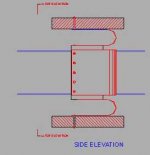
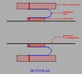
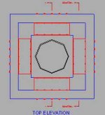
Here's some drawings:
I hope they help. This approach can also work very well for the "cone" surround if the "cone" is rectangular. The only problem for the "cone" surround is the corners, which could be sealed with fabric impegnated with sealant. If you also used this approach for the surround, only one spider would be needed. The flexing plates are shown thick for clarity. The preferable material might be cured sheets of composite, which I suspect you can buy. I know you can buy tubes.... Metal might well work though.
If you needmore drawings of the "cone" approach tell me.
Attachments
here is a pic from CES to further the background info:
scarey application no?
how the heck do they get it to sit still in operation?
scarey application no?
how the heck do they get it to sit still in operation?
An externally hosted image should be here but it was not working when we last tested it.
my god!
a diy acoustic weapon, that is...
At the bottom of the front plate you can see the base plate, which is fairly big (and pretty heavy I can imagine).
But still...
a diy acoustic weapon, that is...
At the bottom of the front plate you can see the base plate, which is fairly big (and pretty heavy I can imagine).
But still...
It appears that they are using the sliding rod approach?
Good thing we have spies everywhere
Is CES on right now? Where are our reporters?
Who is cutting the deals with Manufacturers for group buys?
Good thing we have spies everywhere
Is CES on right now? Where are our reporters?
Who is cutting the deals with Manufacturers for group buys?
Spies ae indeed usefull
Take a look at the spiral springs near the guid rods. That is a method that obviously works. A suspension that is self centering. It pays to keep attention to detail!
Great pics!!
Mark
Take a look at the spiral springs near the guid rods. That is a method that obviously works. A suspension that is self centering. It pays to keep attention to detail!
Great pics!!
Mark
One helluva heavy "cone"
Are there a series of guide rods that are sliding through the top plate???
And that diaphram is thick. Whats it made of???? how heavy??
There seems to be the potential for a lot of frictional losses here.
MArk
Are there a series of guide rods that are sliding through the top plate???
And that diaphram is thick. Whats it made of???? how heavy??
There seems to be the potential for a lot of frictional losses here.
MArk
The friction is mainly why I went looking in other directions than the sliding rods... Are you sure those big flat spirals are centering springs? Maybe they are connections to the coil(s)? prob not, but they look kinda wimpy.
What happened to the pic and are there more????
Having slept and generally having a clear mind today I got to thinking about what I saw in the picture. Not having been there is terrible!! The springs on the sides are progressive in their ability to resist flexture. The start out easy and get more springy ( higher resistance or progressive dampening ) It is a stroke of genius. But we do have some good ideas in this forum. The rods that are currently supporting the diaphram are sliding through the top plate. It can be good or can be replaced by the conventional idea of a surround and basket to control a cone.
Mark
P.S. Nice diagram Variac and it's nice to have someone post good ideas with diagrams so we can all get a grip on them.
more pics found:
http://forum.audiogon.com/cgi-bin/ces.pl?adireaudio&&ManuView
this time not embedded
looks like a teflon guide or similar material through the centre of the baffle... very interesting!
http://forum.audiogon.com/cgi-bin/ces.pl?adireaudio&&ManuView
this time not embedded
looks like a teflon guide or similar material through the centre of the baffle... very interesting!
(1) Still don't see the need for a basket and surround. Seems like a complexity that isn't needed at the moment.
(2) In most mechanisms and systems, you will find that increasing surface area in contact does not increase dynamic friction. Most often, the load between contact surfaces remains the same, and you simply spread the load over a larger area. As the friction per area is directly proportional to the load between surfaces, it is a complete wash. You are left only with the load, and the coefficients of friction. Two or more bushings won't increase the sliding friction.
(3) As counterintuitive as it may seem, two bushings almost always resist binding more than a single one. Alignment of the two is not a problem. A single bushing is more prone to experiencing torsional (rocking) movements, which is the cause of binding as two small contact areas in the bushing take all of the load, increasing friction. Two spaced bushings resist rocking without loading any small areas significantly more than the average. This is the common approach found in most any mechanism, be it in a car, airplane, boat, or kitchen appliance.
(4) Variac's metallic suspension sounds interesting. There should be no problem so long as a material with no fatigue limit (i.e., steel) is used in its elastic region with cyclic stress below the infinite fatigue life stress limit. That is a straightforward calculation which I will make if there is more interest in that direction. May not be able to get the required elasticity in the requisite package size though... need to take a closer look at this to see.
(5) Motor design really should be nailed down first. This I completely agree with.
(6) Still not sure how a central axial rod can be fit inside the pole piece with a bushing traveling on it supported by the VC former. Would the pole piece not really be in the way here? If someone could provide a crude napkin sketch, that would greatly help me in seeing what you have in mind.
(7) With this much stroke, my gut feeling is still that traditional linear suspension elements (springs, bands, etc.) might be more suitable than traditional driver suspension elements (spiders, surrounds, etc.). There is a lot of room that can be utilized to make a fairly simply but effective suspension.
Hello, I'm back from CES, and I have pictures. 😎
Hopefully I can post them right here OK...
I spent a lot of time at the Adire room at Alexis Park obviously, but I also made a few visits to David Moore of Resonant Engineering, one of Adire's close licensees (as they both have intimate ties to a common buildhouse).
I spent some time there, because Resonant Engineering was displaying an XMX subwoofer that was very closely related to the Adire Parthenon...
Using a similarly-scaled XBL^2 motor, but a different design, and using the same "arachnid" suspension - which plays double-duty as the VC leads.
I'm very proud to say, that my suggestions earlier in this thread are actually what RE decided to implement... 😎
That is, no front suspension, panel sweeping against a set of walls, like a piston in a cylinder in a car.
I still suggest that's the best approach here, dipole or otherwise.
They implemented a suspension utilizing just one Arachnid "spider", with their former gliding on a Delrin (similar to Teflon) rod.
My thoughts on the Delrin guide tube are:
1) the unit in the Adire booth, when music was played, chattered along the guide tube, as it was a hand-built prototype, and the tolerances weren't what they would need to be for real musical performance.
2) There's still some friction involved (although I'm intrigued by the idea of building a magnetic guide tube, seems virtually frictionless).
The friction even seemed to counter the restoring force, the former not quite coming to "at rest" again when signal was removed. This particular spider was also absolutely loose, it likely should be much stiffer, also contributing.
3) The centering action could be had by using two spiders ("Arachnid" type of spider seems not only ideal, but the easiest to fabricate! 😎 ), one in the traditional location, and one more located forward of the cone, possibly suspended on the same chassis that holds the "walls" up that our cone would sweep against (if that approach were taken).
Here are some pictures, you may reach the same conclusions as me after viewing them:
Here's a picture of the working Parthenon sub from the front, showing the Delrin guide rod/follower:
Here's a picture of the rear, showing the "Arachnid" combination spider/VC unit (Adire has this patent-pending):
Here's a closer look at the suspension, "at rest":
And a picture with me pushing the cone out about 4":
Hopefully I can post them right here OK...
I spent a lot of time at the Adire room at Alexis Park obviously, but I also made a few visits to David Moore of Resonant Engineering, one of Adire's close licensees (as they both have intimate ties to a common buildhouse).
I spent some time there, because Resonant Engineering was displaying an XMX subwoofer that was very closely related to the Adire Parthenon...
Using a similarly-scaled XBL^2 motor, but a different design, and using the same "arachnid" suspension - which plays double-duty as the VC leads.
I'm very proud to say, that my suggestions earlier in this thread are actually what RE decided to implement... 😎
That is, no front suspension, panel sweeping against a set of walls, like a piston in a cylinder in a car.
I still suggest that's the best approach here, dipole or otherwise.
They implemented a suspension utilizing just one Arachnid "spider", with their former gliding on a Delrin (similar to Teflon) rod.
My thoughts on the Delrin guide tube are:
1) the unit in the Adire booth, when music was played, chattered along the guide tube, as it was a hand-built prototype, and the tolerances weren't what they would need to be for real musical performance.
2) There's still some friction involved (although I'm intrigued by the idea of building a magnetic guide tube, seems virtually frictionless).
The friction even seemed to counter the restoring force, the former not quite coming to "at rest" again when signal was removed. This particular spider was also absolutely loose, it likely should be much stiffer, also contributing.
3) The centering action could be had by using two spiders ("Arachnid" type of spider seems not only ideal, but the easiest to fabricate! 😎 ), one in the traditional location, and one more located forward of the cone, possibly suspended on the same chassis that holds the "walls" up that our cone would sweep against (if that approach were taken).
Here are some pictures, you may reach the same conclusions as me after viewing them:
Here's a picture of the working Parthenon sub from the front, showing the Delrin guide rod/follower:
An externally hosted image should be here but it was not working when we last tested it.
Here's a picture of the rear, showing the "Arachnid" combination spider/VC unit (Adire has this patent-pending):
An externally hosted image should be here but it was not working when we last tested it.
Here's a closer look at the suspension, "at rest":
An externally hosted image should be here but it was not working when we last tested it.
And a picture with me pushing the cone out about 4":
An externally hosted image should be here but it was not working when we last tested it.
- Status
- Not open for further replies.
- Home
- Loudspeakers
- Subwoofers
- DIY Parthenon