That's certainly frustrating Paul!
I guess/hope there will be some sources somewhere that can supply though.
For the rails, weight doesn't matter and certainly a pair of rods, carefully assembled could work well.
I glued my stainless steel ones to a carbon plate, paying careful attention to flatness.
Anodised aluminium is easily hard enough to work satisfactorily, i have run many test and use hours and seen no marking at all.
One can obtain hard anodised aluminium and special coatings like teflon as well, and that is one route i have yet to try. i have handled some examples and it seems likely the coatings fill some of the micro sized dips.
I found a local supplier who would coat all the arm parts i need for £100, but i haven't made any yet!
I recommend you build a carriage with commercially available anodised angle and get a feel of that set up.
Materials in contact interact depending on material types and the forces between them may be more important than simple hardness and flatness.
Good luck
M
TwinArm - a passive servo linear? #5480 to #5525
Another step of my box kicker method - some more due infos.
c
Another step of my box kicker method - some more due infos.
c
Attachments
Last edited:
Paul, whilst you're gathering thoughts i would like to introduce you to 4 other areas you might consider (or discard!!)
Wiring, leverage, levelling and vertical orientation.
There have been a number of explorations on thread here that are of interest.
1. Wiring is probably an easy one, many folk, including me start out with something available and rapidly find springy wiring is a significant failure.
I followed Niffy's advice and use two spiralled cores per pole all wrapped in a sleeve of three cores of screen, so 11 cores in total of fine enameled magnet wire, you may have found the references already. With this there is no perceptible effect from the wiring.
2. The much used wand and carriage asks the stylus side force to move the carriage on a long lever, like pushing a car to and fro with a pole out the side, rather than pushing it on axis, Radial arms where the carriage is above the stylus remove this lever.
3. Levelling your arm will be critical, way more critical than any bubble will show you, and so also stability of your TT/carriage base set up in level will be important. so, locking the arm in vertical orientation (balanced level, stylus off the record) you can adjust for level travel.
4. On a wand the cartridge will change its vertical orientation to the record constantly with factors such as record thickness and warp. Carlo resolved this with several of his RTA's with a solution for leverage at the same time. In my opinion these are well worth a study.
M
I am writing via Google Translate.
Greetings from Russia.
I am in awe of your work.
I have a question and would like to ask you to clarify.
How do you solve the problem of dust on the carriage guides? There is always dust in the air.
Hi Andrey, Sorry for the late reply I have been away. I don't have a dust cover over my TT and I do wipe the rails occasionally with a cotton bud. I haven't had an issue with dirt on the rails causing problems. Dressing of the wiring harness is more important and if not done correctly can cause the stylus to skip.
cheers Warren
The track rod is only 4" long? I would think it would need to be at least 8" (4" of grooves + 2" on each side for the carriage). What have you found to work best for the bearings? Dry / lubricated, sealed / open, ceramic or metal?
I think I'm going to start with Colin's original design (as close as I can replicate it) and see how well it works. I may also do some experiments with the ball and track approach as an alternative / backup.
Hi Paul, I'm a bit late to this conversation. I think building the original design is a good idea as it works extremely well. My first build was the version 2 with dual glass rods. If I was doing this again I would use linear shaft it's inexpensive and if you buy good quality also straight.
I used off the shelf ball race bearings. Removed the dust covers and removed the grease. If you spend a bit more you can buy fishing reel bearings that use dry race, these are sold for casting competition.
Hi,
@Mike56 "
1. Wiring is probably an easy one, many folk, including me start out with something available and rapidly find springy wiring is a significant failure.
I followed Niffy's advice and use two spiralled cores per pole all wrapped in a sleeve of three cores of screen, so 11 cores in total of fine enameled magnet wire, you may have found the references already. With this there is no perceptible effect from the wiring."
That sounds as quite a lot of copper and stiff wiring for such a small wire... But then I have to admit that I quite don´t understand the recipe in fullness.
Do You have a sketch or pics of the construction or more info about it?
Thanks
Calvin
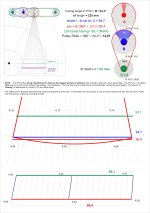
And 5291 gives a picture. To give a feel of the flexibility, this is about 175mm long in my set up and moving the connector end from one side of a record width to the other will not "pull" the carriage, despite the low friction. There is enough form in the group to retain the spiral shown. There is no perceivable hum now with shielding as described.
A satisfactory solution for a few cents of wire and some simple work.
M
I did then make a capacitance selector set for my preamp and measured the frequency response to choose an optimum, but that's a different story!
A satisfactory solution for a few cents of wire and some simple work.
M
I did then make a capacitance selector set for my preamp and measured the frequency response to choose an optimum, but that's a different story!
Hi,
unfortunately the link in #5281 just points back to #5281. But a copy and paste search lead to the wire´s website.
So if i understand it correctly for each pin of the cartridge there is a twisted pair of the wire (in sum making it 4x2=8 wires).
One additional wire per twisted pair for screening ... makin it 12wires.
All of this is then twisted into one single cable.
Is that right so?
For my tonearm I used a similar approach (from my website, see TheKiller):
"I use as thin and flexible silk-spun copper-litz wire (in sensible compromise with the wire resistance) internally in the arm, utilising fixed soldered cartridge connectors and a decent connector.
External to the arm I use good quality coax-cables leading to the Phono-preamplifier.
HF-Litz wire has proven to be useable as strands, e.g. silk-spun 7x0.05mm (7xAWG44 ~ AWG36), of which I twist two together for a single strand.
The plus- and minus strands of each stereo channel are then twisted together also.
Done this way the strands are low enough in ohmic resistance and mechanically very flexible.
The twisting does increase the capacitance of the strands, but the resulting 50-60pf present no issue.
In my opinion the advantages outweigh the small disadvantage that the twisting generates.
Both stereo channels are clean separately positioned in the armtube to avoid interchannel crosstalk.
The bottom of the arm shaft holds a connector that is a variant of the DIN-connector.
A locking nut and sensibly designed contacts guarantee for a safe and sane connection.
As cable between arm and phono-preamplifier either a a well screened low-capacitance coax cable, or a balanced microphone cable is used.
Since the strands within the arm are unshielded, some means of shielding must be supplied for. By using metallic parts and a carbon arm tube a electrical connection exists from the headshell down to the arm shaft.
The connection though passes the ball bearings and due to this it is not reliable.
Therefore a threaded bore is drilled into the bottom side of the bearing cross, between the gimbal and the counterweight.
A eye is screwed on, to which a piece of stranded litz wire is soldered, that terminates in the PE-contact of the DIN-connector. This way a good shielding and reliable PE-connection is achieved."
I tested variuos different silkspun wires with different combinations of wire count and thickness per strand.
Strands with lower wire count but thicker wires gave stiffer cabling, as well as higher wire count with thinner wires did.
In the end the 2x7x0.05mm twisted wires appeared optimal.
The tight twisting increased the flexibility of the wire considerably, even though the wire now looks quite thick compared with standard litzes.
For MM cartridges a thinner litz, resp. lower number of strands, resp. a higher wire-resistance would have been ok.
But especially for low-output MC-cartridges the wire resistance should be low to keep losses of signal voltage small.
One could argue that with the low impedances involved here a MC cart might rather be viewed as a current source than a voltage source.
The truth is probabely lying inbetween .... so one should still have an eye on cable resistance.
jauu
Calvin
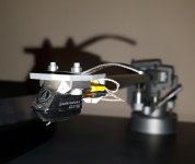
ps. unfortunately I´m no photographer and I also always forget to takepics while working on projects .... so this is the only wire pic I found.
second is my classic-tracker style tonearm.
unfortunately the link in #5281 just points back to #5281. But a copy and paste search lead to the wire´s website.
So if i understand it correctly for each pin of the cartridge there is a twisted pair of the wire (in sum making it 4x2=8 wires).
One additional wire per twisted pair for screening ... makin it 12wires.
All of this is then twisted into one single cable.
Is that right so?
For my tonearm I used a similar approach (from my website, see TheKiller):
"I use as thin and flexible silk-spun copper-litz wire (in sensible compromise with the wire resistance) internally in the arm, utilising fixed soldered cartridge connectors and a decent connector.
External to the arm I use good quality coax-cables leading to the Phono-preamplifier.
HF-Litz wire has proven to be useable as strands, e.g. silk-spun 7x0.05mm (7xAWG44 ~ AWG36), of which I twist two together for a single strand.
The plus- and minus strands of each stereo channel are then twisted together also.
Done this way the strands are low enough in ohmic resistance and mechanically very flexible.
The twisting does increase the capacitance of the strands, but the resulting 50-60pf present no issue.
In my opinion the advantages outweigh the small disadvantage that the twisting generates.
Both stereo channels are clean separately positioned in the armtube to avoid interchannel crosstalk.
The bottom of the arm shaft holds a connector that is a variant of the DIN-connector.
A locking nut and sensibly designed contacts guarantee for a safe and sane connection.
As cable between arm and phono-preamplifier either a a well screened low-capacitance coax cable, or a balanced microphone cable is used.
Since the strands within the arm are unshielded, some means of shielding must be supplied for. By using metallic parts and a carbon arm tube a electrical connection exists from the headshell down to the arm shaft.
The connection though passes the ball bearings and due to this it is not reliable.
Therefore a threaded bore is drilled into the bottom side of the bearing cross, between the gimbal and the counterweight.
A eye is screwed on, to which a piece of stranded litz wire is soldered, that terminates in the PE-contact of the DIN-connector. This way a good shielding and reliable PE-connection is achieved."
I tested variuos different silkspun wires with different combinations of wire count and thickness per strand.
Strands with lower wire count but thicker wires gave stiffer cabling, as well as higher wire count with thinner wires did.
In the end the 2x7x0.05mm twisted wires appeared optimal.
The tight twisting increased the flexibility of the wire considerably, even though the wire now looks quite thick compared with standard litzes.
For MM cartridges a thinner litz, resp. lower number of strands, resp. a higher wire-resistance would have been ok.
But especially for low-output MC-cartridges the wire resistance should be low to keep losses of signal voltage small.
One could argue that with the low impedances involved here a MC cart might rather be viewed as a current source than a voltage source.
The truth is probabely lying inbetween .... so one should still have an eye on cable resistance.
jauu
Calvin
ps. unfortunately I´m no photographer and I also always forget to takepics while working on projects .... so this is the only wire pic I found.
second is my classic-tracker style tonearm.
Attachments
Last edited:
"unfortunately the link in #5281 just points back to #5281. But a copy and paste search led to the wire´s website.
So if i understand it correctly for each pin of the cartridge there is a twisted pair of the wire (in sum making it 4x2=8 wires).
One additional wire per twisted pair for screening ... makin it 12wires.
All of this is then twisted into one single cable.
Is that right so?"
Almost exactly Calvin, the only difference being that after first twisting together the wires for the individual conductors and then the two channels I used three (not two as you described) screen wires which are loosely plaited round the channel conductors as screen. These are connected to ground only at the output end which is the input to the preamp.
I also had to make resistance and capacitance adjustments in my set up as this is different to what would normally be seen.
It is difficult to see in photos but your wires look more chunky than mine, no doubt because of the insulation, the magnet wire depends just on its coating.
I see a similar twist, I mount a few metres in a hand drill to get a nice even twist and then cut parts from the long section as the group is assembled.
In my radial arm the characteristics of the wire are critical to allow free movement.
Now, off topic, but really interesting, your arm, the link to your site and so on, all looks great!
I see you describe a cardanic joint on your 12" which is also an elegant principle.
Carlo will surely be interested as well.
I havent read all parts but it looks like youve worked through all parts of the audio chain.
Your notes stop after trying to obtain a third party validation, did that complete, how does it all sound?
Best
Mike
Hi,
thank You so much 👍
Here are two links to the german AAA forum.
TheKiller is dealing with my own tonearm ... giving detailed descriptions and offering some more pics.
TA1 - Tonearm is the follow up with some nice mods from the user Köter who fabricated the parts of my tonearm.
That thread includes many more good pics .... only in german of course, but a translator should give some reasonable output.
Köter and me have had a number of shared projects -quite successful and nice looking I might add. 😉
After this short OT now OT again 👍
jauu
Calvin
I have to sign up to see the pics, so i will work on that!
The prompted translator seems fine.
Meanwhile, did you ever try a linear or radial TA project?
M
The prompted translator seems fine.
Meanwhile, did you ever try a linear or radial TA project?
M
Hi,
too bad :-(
Yeah, for years I have a slotted quarz glass tube lying around for a linear arm with roller bearings running on the inside wall of the glass tube.
There are threads about a commercial incarnation of this kind of arm (which I have forgotten the name of) with some DIYers here having built someting like that.
jauu
Calvin
- Home
- Source & Line
- Analogue Source
- DIY linear tonearm