Great work Doug!,
The arm looks very good, and the bearing arrangement performs surprisingly well doesn't it?.
Directdriver, you could use two u groove bearings but I must say this was my original thought, but bearing weight is not a real concern since it is a fraction of total weight and as along as the mass below the bearings far exceeds the bearing weight it's a moot point. In this design you actually want to place a good chunk of weight at and behind the bearing axis since this help to counter the wand and cartridge weight, it's all about where you place it. I must add that the reasoning behind standard bearings is anyone can find these which makes the arm access able to anyone within reach of a hobby shop to build, standard parts which I believe adds to the project and since rc car enthusiasts are competitive you are guaranteed low friction 🙂, even off the shelf for the small diameters.
Colin
Last edited:
Doug,
With a brass tube there are a few issues.
The brass tube is nowhere near as flat or smooth as is glass.
The other issue is brass is soft, very soft compared to the steel on the races. Not a good combination.
The glass is hard compared to the steel, so the steel bearing races tend to slide, not polish or dig in.
At the very minimum, I'd mirror polish the brass rod, easy to do. Better still, chrome plated would be better than straight brass, since chrome is very hard.
Although it is not a popular idea, if brass was employed, I'd want to opt for a very very fine layer of lube on the surface.
The edges on the "U" bearing races are sharp compared to the outer edges of the preferred bearings used on top of the glass, more likely to want to dig in. Other than that I like the "U" bearing idea too... the dust shields likely add friction to this bearing, fwiw...
And also, even though these are hardened steel races, the outer edges and surfaces can be polished. One would need to make up an arbor that holds the outer (like between two precisely sized washers) and spin it, hold the appropriate fine AlO paper (2400 grit for example) and then maybe polishing compound as it is spun fast. A lathe is ideal, but a dremel type tool would be good enough. Drill press and hand held drill not as effective but maybe useable.
A fine mirror finish on the bearing outer surface will only reduce the friction when sliding on the tube... (or in the tube). Assuming this is the desired outcome, that is...
bear,
You write;
"A fine mirror finish on the bearing outer surface will only reduce the friction when sliding on the tube... (or in the tube). Assuming this is the desired outcome, that is..."
The condition of the contacting corners of the outer races is an issue I have been yapping about for years in these threads. Nobody seems to have noticed. Less than an excellent smooth surface will effect rolling friction as well as sliding friction. As a minimum I check these corner surfaces with a loupe and a fingernail when selecting bearings and reject any showing roughness at all. Polishing with rouge could be beneficial. Be sure to flush out the polished bearing well to remove any residual rouge that may have crept into the bearing!
BillG
Rouge or other suitable compound... yes... agreed.
My wording is a bit ambiguous, when I said "only" it might have been better to say "will serve to reduce"... clearer I think.
My wording is a bit ambiguous, when I said "only" it might have been better to say "will serve to reduce"... clearer I think.
Update on recent carriage,
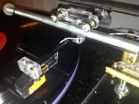
After some listening, this is much better than the epoxied two wand arm!. The only part glued now is the headshell with super glue, using the right drill bit I'm able to bore t out enough for a tight press fit, the glue just sites it. The wand is .220" carbon fiber tubing that is one straight piece. The counterweight is slung so that its mass now hangs just below the top of the cartridge, the better energy transfer is instantly noticed in the bass, bloody solid and deep!, along with inky black background in quiet pressings. The bearing piece that holds the wand is cut in a T from 10mm polycarbonate with a set screw to lock azimuth and arm wand.
Colin
Attachments
Bear,
I lashed that arm together from stuff, including the brass tube, that was around my shop. I've used metal tubes before as first approximations. If an idea works even somewhat, it may be worth pursuing. Even with the brass, the performance of Colin's design is impressive. I think I can pick up a glass tube locally. If not, I can get stainless steel.
As built, a more pressing consideration is that it's about 10 gr. too heavy, but I think that can be dealt with.
BillG,
I'm not quite sure why, but dry bearings, even free spinning ones, like you and I are used to using don't work well on this design. The improvement when I switched to sealed lubricated bearings was significant, in fact it pretty much wouldn't work without them. Both sets were ceramic hybrids.
Colin's point about the geometry of this arm being critical is worth paying attention to. The arrangement of the bearings on the tube and the relative positions of the headshell and CW are important.
For me, Colin's design is an object lesson in not rejecting possibilities on theoretical grounds. I was playing with a carriage idea that involved either three or four bearings but dropped it because, without doing any testing, I decided there would be too much friction.
Doug, that's fine that you built an approximation for testing, but a casual reader won't know that. So, someone randomly reading might assume that brass is fine, and easier to find, and deal with and go right with that.
I think that in all likelyhood something like glass is required. I doubt that stainless is going to be hard enough to really do the job properly. You'd see marks develop on the stainless over time I'd expect... with a really good polish (mirror finish) and a hard alloy, and maybe a surface lube using synthetic lube, that might fly, imo. Folks have said that lubes attract dust and dirt and that messes up the horizontal motion.
Others have found that dry bearings have lower friction, and bearings with the dust covers on have highest friction. So, it's puzzling why the ones with the apparently higher friction are working better? Did you compare "spin time" by any means?
What did the arm do when the other bearings were installed? Not move horizontally?
how to mount
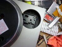
On a technics SL 1800, the tone arm was originally mounted to the bottom half of the plinth which has some sort of suspension system on it. Will I get away with mounting on the top half or will I have to adapt the existing mounting pillars on the bottom half?
AND
I take it we are after a wand length of about 2 to 2.5 inches
Attachments
Not sure why I keep posting to this thread... heh. Kinda fascinated with the simplicity of the design.
But the relationship between the arm and the record surface needs to be 100% stable. I think this means that isolation via a suspended undercarriage is out for this sort of design.
However, they may have gone to this because there is an issue with the mechanical noise of the TT motor itself that was being transmitted to the arm... otoh, was this an automatic pick up or drop arm system? That might account for the mounting set up too.
After mounting on the top I think you'll want to do something for increased isolation between the TT and whatever surface you have it sitting on top of.
One method that is very inexpensive and works well is a sand box.
Fine sand in a box, with a flat surface sitting on top of the sand upon which the TT sits.
Bear,
You're right. It would have been better to mention that the brass tube was only for experimenting so no one was mislead.
All of the bearings, both sealed and dry, are ceramic hybrids from Acerracer and the dry bearings have been used successfully on other LTs. The dry bearings were cleaned with acetone and spun with compressed air. The spin down time was between 10 and 20 seconds. The sealed bearings have essentially no spin time. The whole thing is seriously counter intuitive, but in practice the sealed bearings worked and the dry didn't. The dry bearings barely rolled and stuck badly while the sealed rolled freely (mostly, not always). My best guess, and that's all it is, is that the difference is "stiction" rather than friction. It's also possible that with a glass tube the relative bearing behavior may change. Another possibility is that I mounted the bearings differently than Colin did. Because I don't have any 5 mm OD brass tubing I wasn't able to use Colin's "shim" technique, which he has said is important to his design. There are definitely devils in the details of this arm.
Colin,
Thanks for your reply. Your recent iterations look better and better. The stability of the four bearing carriage is impressive when it's built right. That took me a while, but, yes, it was a pleasant surprise when I finally got it.
I have to read everything again more thoroughly, but Doug, you're using sealed lubricated
bearings, while everyone else is using dry bearings.
It's stuff like that that makes my head hurt ..... 🙂
bearings, while everyone else is using dry bearings.
It's stuff like that that makes my head hurt ..... 🙂
Jan,
My apologies for your head. When Colin said he was using sealed bearings, steel on steel no less, (check post #8 on the first page) I was extremely skeptical. I've used dry ceramic hybrids for previous projects and they worked well there, but to my surprise they did not work in this design and the sealed ceramic hybrids did.
A possibility that just occurred to me is that in my previous projects the sideways forces on the the bottom of the bearings are minimal and equal. In Colin's design that force is inherently pushing one side outward from the glass tube and is trying to twist the bearing in a direction it doesn't want to go. The seals and lubrication may help keep the bearings stabilized and free to turn.
Colin?
Something I haven't mentioned yet: This arm sounds very good and has all those mysterious LT qualities that keep people so fascinated.
Last edited:
If I may ask, what kind of sealed hybrid bearings are you using?
I'm guessing that the cartridge used will also influence what kind of bearing is most
suitable?
I'm guessing that the cartridge used will also influence what kind of bearing is most
suitable?
Jan,
I'm using inexpensive ceramic hybrid RC car bearings from Acerracer, which is online and ships free world wide. I used them because they were on hand and the right size. You might check out SKF bearings. Posters on the "cantus" thread reported good results with them.
Colin's arm successfully uses steel bearings so I'm pretty sure bearing quality and size are more important than material or source, which I hope makes the bearing decision easier.
In the past, I've used a Shure M91ED, which because it's a high compliance cartridge is a real test for LTs. The AT95E, which I used this time and I think Colin used at first, is a lower compliance cartridge and seems to be a better match for this kind of arm.
Last edited:
I'm using these type of bearings in my design, so, hopefully, I will be able to say whether they work, or not. I intend to run them on 4mm carbon fibre rod.Will two intentionally undersized U-grooved bearing work, instead four flat bearings? Two undersized U-grooved bearings on a rod will represent as four contact points just like Colin's arm but reduces mass and less ball chattering perhaps?

Doug,
I must thank you for helping me not look too much like a lunatic, haha. I never tried dry bearings since the off he shelf bearings were working fine. You are right the devil is in the details, the geometry, weight distribution and such. The newest arm is the best yet aside from looks, and I've addressed some further setup adjustments that lacked on prior versions the most important being azimuth.
Directdriver, I welcome you to use whichever bearing you choose 🙂, though of course that becomes your design with u groove which would no longer be this bearing setup as such. I however would love to know the results !
Colin
Hi Doug and Colin,
Last night I made up a new carriage. Two new 4 x 10 x 4 ceramic hybrids, lubricated as they come from AcerRacer and two taken from my last carriage. These were running clean and dry so I cleaned them again and lubed them with a tiny drop of general purpose clock oil. Followed that with a spray of WD40 to thin the clock oil a bit. (This is a temporary lubrication). I try to avoid WD40 like the plague. Mounted a 10 mm glass tube in an old experimental LT arm and today played a few records. I still don't believe my eyes and ears. Everything you guys say is correct. I'll be saying more soon after using this for some time. Have to be out of town for a few days so I won't be able to use the arm till after I get back. I will have access to the web though so I may comment on your posts.
Looks like there has to be some serious analysis to explain why Cantus linear trackers have to be run with dry bearings or conversely why these 4 bearing designs don't want dry bearings. I'm buffaloed for now but pleased with the development.
BillG
Jan,
My apologies for your head. When Colin said he was using sealed bearings, steel on steel no less, (check post #8 on the first page) I was extremely skeptical. I've used dry ceramic hybrids for previous projects and they worked well there, but to my surprise they did not work in this design and the sealed ceramic hybrids did.
A possibility that just occurred to me is that in my previous projects the sideways forces on the the bottom of the bearings are minimal and equal. In Colin's design that force is inherently pushing one side outward from the glass tube and is trying to twist the bearing in a direction it doesn't want to go. The seals and lubrication may help keep the bearings stabilized and free to turn.
Colin?
Something I haven't mentioned yet: This arm sounds very good and has all those mysterious LT qualities that keep people so fascinated.
Bgruhn,
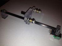
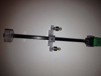
Awesome to hear that you put the concept together, even quickly thrown together the benefits are instantly noted!. I am very happy with the way the bearing arrangement performs, the spacer is definitely important and part of the success of this arrangement, brass is preferred of course since its softer than steel. With the newest pics you can clearly see the arrangement. I still can't get over how much better transients are, with any pivoted arm I've tried the sound is nice, dynamic but always seems to smooth out the transients leading edge smearing impact, some to a lesser degree than others. I guess it's a case of when it works right, linear arms have the edge over pivoted arms 🙂.
Colin
- Home
- Source & Line
- Analogue Source
- DIY linear tonearm