As i have done this allready i know the heatsink will cool down slowly becouse of the mass off the 15mm thick base.
It takes presumably 3 minutes for the solder to get hard.
Heating is also no problem with the 7.5 kW plumber torch that i own.
To be precise it is really to much.
Whith this torch you can actually burn the solder by overheating the sink if you are not carefull.
I did place the sink on a flat heat resistant surface but still the sheets move up and down.
Try to put a couple off sheets together with grease between and clamp them, you will get the same result.
Maybe a more liquid flux will do.
As english is not my native language i do not know how to make myself more clear.
I will take some pictures in the next week so you can see my sink.
Merry christmass to you all.
Edwin
Drill two holes through the stack of plates then put a guide pin in them to stop the up-down movement.
One more tip
Most of the work in a large soldering or welding job like this is the setup of the project. It is very difficult to clamp up small pieces of metal when they slide against each other covered in solder paste (grease) What I usually do is set up a jig to hold the hole mass together gentle. How this is accomplished is by making a "U" shaped cut in a piece of wood that will just allow a snug fit of the whole assembly of pieces carefull measurement is needed. An alternative to carefull measurement is to cut the "U" wider and make two wedges that placed thin to thick end will make an adjustable parallel spacer. When hammered in this will provide all the claping pressure that you need. This stops three sides from moving around. If you made the cut with a table saw the fourth open side can be clamped with the part of the wood that you cut out to make the "U" shape opening that the heat sink fits into. A standard F-clamp or fast acting clamp or whatever you have will do the job of applying pressure. Don't try to clamp things to tightly as this will not help you. If you see the proper shape and form the solder will fill in any voids that are left.
I understand the torch that E. Pardaans has will heat up the metal. But I still know that a slower even heat with localised warming will turn out a better job. The clamping idea when executed properly will work well. The pieces will be all smooth or flush to one side and there will be a minimum of machining needed.
On more note on the machining. It can be done carefully and with small cuts with a router in a jig that is a couple of centimeters higher than the heat sink. Two parallel pieces of wood on either side of the heat sink and a flat board that the router is screwed or bolted to allows a larger base that you can slide over the width and height of the heat sink. The metal must be clamped down firmly and the cuts very lite or small in depth. About .3 to .5 mm depending on the diameter of the router bit. I sugest no larger that 12mm diameter. Watch your eyes for metal pieces flying around.
Mark
Mark,
how fast can the router go ?
I find it tricky to keep a steady speed with my ELU MOF96 when milling wood.
Any suggestions ?
how fast can the router go ?
I find it tricky to keep a steady speed with my ELU MOF96 when milling wood.
Any suggestions ?
First of all, think about the heat conductivity of solder..... It's not exactly good. But if you are able to get a good heat distribution and it works then why not.
Ok, what I would do is to do as mentioned by someone else to drill holes in ALL the pieces at the same relative place and use a long screw or a threaded bar (or whatever you call it). This I would do WITHOUT applying anything. Right now you should already have a nice and usable heat sink.
But you will gain by making sure the surfaces in contact with metal are clean and evenly surfaced.
Then if you want to use solder you should definitely use silver solder. First of all it is about the best thermally conductive material to solder with, and it is much stronger. It will also not be damaged as easily by overheating it. It's possible to use oxy acytilene torch on it without problems!
And you should try to use the capillary effect too. This way only the needed amount of solder is sucked in to the joint, and there are no trapped air bubbles or contamination inside the joint (where the heat transfer is going to occur). To get a good capillary effect there is a small distance needed. I'm no expert, so the best thing to do is get advice from someone experienced in hard soldering.
And about preheating. If you try to heat the assemblies to a temperature above the melting point of tin/lead solders and apply it on the joints preferably while keeping the ***. heated that could also work. And I think the idea with the stove was to put the whole thing in the stowe for a long enough time for the whole assembly to be evenly heated.
What methods that will be best have to be tested, but to me this sounds like quite a bit of work!
I wouldn't do it like this unless I already had all the materials for free, and there was no other way.
But I think using a screw through a hole holding the pieces together is the key to success here!
Personally I’m going for water cooling, and I have access to a CNC mill to make it too 😀 And hopefully some cool chaises too go with them too. 😎
Killjoy99 said:
This design does not use any forced convection (no fans) but I'm also not sure about the particular heat generated by the processor it is attached to.
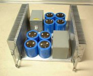
To me these heat sinks definitely looks like they are made for forced convection. This is because of the close distance between the plates. And it is probably a heat-pipe design too. It's not possible to see from the picture, but the way the central heat-spreading made like a thick vertical tube makes it the most probable design.
That close spacing between the cooling elements will not give you much natural convection. The fact that it is aluminum and not eloxated black is another sign that it is meant for forced convection. Remember that it is from a server, and they normally have huge fans at the back of them. They are meant to be placed in server rooms and other places that noise isn't that much of a concern, and are most often much noisier that normal computers. Normally there is a constant flow of cooled air forced through the servers in a good server room.
And if it is a heat-pipe remember that they only have a certain capacity before they get overloaded (and then they are worse than ANY normal heat sing, small or large!). For a CPU cooler that could be more than 200 W though, but it has to be taken in to account!
Just thought I'd inform you so you (and others!) don't get your hopes up to high to fast (not that it' not a great heat sink....... it is, you just have to know how to use it and how NOT to use it)
Just at tip.
With an LM317 it is easy to get an accurate measurement for the thermal resistance of a DIY heatsink.
The LM317 package should be placed on the heatsink and fed with a 20-30Volt/3 amp powersupply.
The LM317 has a thermal protection circuit to limit the current when the PN junction reaches 125 C.
After 15 to 30 minutes voltage and current through the LM317 is measured with a DMM, resulting in the number of watts going in the heatsink.
Measure ambient temperature and fill in the data :
125 - T(ambient) / ( volts * current) = Rja
Subtract from Rja the thermal resistance of the LM317 and thermal resistance of the glimmer disc between heatsink and LM device, what remains is the heatsink's thermal resistance.
In case of need for an accurate number for the glimmer disc, two measurements can be done.
One with isolation, one without.
Rglimmer = Rja(with glimmer)- Rja(without)
I refer to basic Q - I've had an idea to build them - but in my case - as somekind of a reference because of ratio beetwen what you pay and what you get a have Fischer's SK 56 - you can see it here - I've calculated it's more expencive for me to build it myself. I mean - e.g. PeterD's heatsinks in his Zen - he payd more than 70$ just for those little heatsinks if I understand him correctly ...
(e.g: two pcs of SK56 with 200mm height and allready black eloxated costs me around 70$ and are good enough for stereo A5 or mono A2)
(e.g: two pcs of SK56 with 200mm height and allready black eloxated costs me around 70$ and are good enough for stereo A5 or mono A2)
how fast can the router go ?
A router is basically a rotary chisel or plane. The cut depends on the power available, the size if cut both in diameter and depth, and the cutting angle and degree of keeness. All these things work against you. When milling metal I usually use a solid carbide cutter. THey are available from wood working suppliers. Sometimes they are much cheaper from metal working suppliers. They have the proper shear angle to actually cut and lift the material off the surface of the work piece. This leaves you with a better finish on your work piece and is easier on the motor of the router. The depth of cut of course depends on the power you have and the feed rate that you are trying to push the router through material.
These things must be balanced to work properly. A smaller router can make good cuts in softe metals if they are very light. Or in wood if they are in turn very light. Listening to the router will tell you when you are pushing to hard. If it is labouring you should of course take lighter cuts. Basically common sense but I write it here for those who don't do this work often.
Mark
The heat conductivity of solder doesn't matter if the sink is made up of lots of plates stacked, and the edge of each plate touches the part that requires cooling. This approach is mentioned earlier in this thread.
Restrictions in air-flow would cause problems in this configuration.Grandma´s_SUB said:What about W-shape?
Hot water?
Hot water base board heat exchangers come in a variety of sizes and are designed for very high efficiency of heat transfer. Besides a liquid cooled amplifier is just too cool! Large copper tubes permit a copper plate to be attach to the plumbing with silver solder for easy mounting of you output devicesand provide excellent heat transfer. Just a few degrees (about 5-7) will give convection. Water could be used but just to avert a disaster in the event of storage in sub zero it would be wise to use antifreeze. You will need a fitting to fill and seal and a small saftey valve. This can be done in a largre bucket or small drum. If you spray paint the fins with a black heat paint you can increase the thermal capacity further. It's also a good idea to run a bead of sealant along the middle of the length of the fin plates on the lager square plate designs. This keeps them from making pinging noises as they heat up and move on the copper tube. Either straight sections or cone shaped coils like the type used in some air conditioners could be used. A small cone with one of those cool computer fans with the fancy LED light arrays would look very interesting housed under an open chrome wire cage. These things are almost free which is an extra bonus.
Hope this spawns some ideas out there. Best regards Moray James.
moray james; Can you attach some schematic diagram?(maybe it is very easy to understand if you speak ENG well,but if you not,you need diagrams 😀)
vdi_nenna: Nice job.Did you use that(attached) design?
-That design requires a lot of precision at drilling holes...one mistake means a lot of whetting,or here we go again
vdi_nenna: Nice job.Did you use that(attached) design?
-That design requires a lot of precision at drilling holes...one mistake means a lot of whetting,or here we go again
Attachments
Looks to be the same design. The heat sinks were made by using a mill. There are no saw cuts. I used John Inlow's design...can't remember his web site at this time.
BTW- Neil didn't say that exactly. He said "Small step for man, one giant leap for mankind." He forgot the "a" for a man... But then again, under the circumstances, it's understandable. 😀
"Small step for a man, one giant leap for mankind," Neil Armstrong, 1969.
BTW- Neil didn't say that exactly. He said "Small step for man, one giant leap for mankind." He forgot the "a" for a man... But then again, under the circumstances, it's understandable. 😀
mill?WTF?Isnt that that device for making a cofee?(English problems again)
-please,attach John Inlow's page
-please,attach John Inlow's page
- Status
- Not open for further replies.
- Home
- Amplifiers
- Pass Labs
- DIY heatsinks