'helped', possibly, but i think i read somewhere that a weld joint has different thermal properties than the base metal pieces. so even with welding i think you still have a bit of a 'layering' issue.
a weld may differ from the base material, but a simple heat treatment will solve such a problem....i believe most ovens should be able to go to around 400C, leave the heatsink to soak the heat for a couple of hours, throw it in a bucket of water and it will be 99% homogenious.
From this treatment youd gain another benefit. For a few hours the aluminium will be soft after this treatment, so it will be much easier to bend the finns into shape. When the finns are in the right place, simply leave the heatsink at room temp. for about a week, and it will harden up to the initial hardness.
Magura
crap, that's what i do all day anyway.
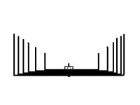
ok i needed a break...here's my grand vision. 75mm fins. 1mm thick. total width 150mm. the stuff at the 'spine' is for e.g. a transistor screwed in - you'd have to tap a hole to mount it of course.
i'm not going to draw one with a 'spine' piece, it's easy enough to imagine it.
/andrew - doesn't have an oven that goes to 400C.
Attachments

faustian bargin said:
/andrew - doesn't have an oven that goes to 400C.
And then again...i guess Andrew does have an oven that does 400C....a baking oven with the grill turned on ends up around 350 to 400C
Magura
(350C * 9 / 5 ) + 32 = 

 662°F ...maybe, i dunno that's pretty high. 500F is the broil setting AFAIK.
662°F ...maybe, i dunno that's pretty high. 500F is the broil setting AFAIK.Ohh, thats different in the USA then, in europe its common to be able to take it to 350C+ the grill element on.
My mistake 🙂
Magura
My mistake 🙂
Magura
Way to go Andrew! The "Mirror" command is your friend 😀
Thats just what I was imagining. Now all DIYers around the world have to focus on where there are lots aluminum rectangles sitting around for cheap. Some kind of packaging maybe- I don't think they have to be 1mm thick if there are enough of them. Of course you could cut up a bunch of soda cans, for the ugliest sinks ever!
If you cut off the ends, and a cut up the side, they would even have a curve already... sissors work fine.
The cleaning cycle of ovens gets really hot but you can't open them until they cool down 🙄
I'm starting to get swamped with arch. projects-maybe we should talk shop someday. Mainly I'm swamped because I had 6 weeks of jury duty, but I've got some nice houses suppposedly coming up......
Mark
i'm not going to draw one with a 'spine' piece, it's easy enough to imagine it.
Is this referring to the clamp bars that need to be under the bolt heads and nuts to compress the leaves evenly?
Variac said:No, the point is we don't want to deal with heat transfer between layers. The design is not fully scalable. The spine can only be as thick as the combined width of the staggered devices.
The edge of each sheet must contact the back of at least one device for this to work optimally. Of course it will probably work fine if you add a few layers and count on some heat transfer, but this isn't optimal.
There are solutions to that, at least for us amp builders. Remember there is nothing that dictates that all the transistors have to be on a line and on the same fins. That is unless you are building a 4 transistor version with 4 separate heatsink assemblies monoblocks. One TO3P transistor is about 20 mm, but if you place them in a way that each one have their own main fins (the fins they are directly in contact with).
BTW nice drawing Faustian! 😉 Exactly how I meant!
But you don't have to be limited to a half circle shape. By adjusting the length of each blade other shapes can be achieved, like a rectangle. That could probably be easiest done by cutting the pieces to size before assembly. That way you can put them closer together.
About welding.... aluminum is not the easiest metal to weld exactly..... And you need special equipment. I think baking it in the oven makes much more sense. And if anyone of you make an attempt to make one in the sizes talked about here I would recommend using as thick and robust spline bars as possible, and NOT in aluminum. A 20 X 40 mm steel bar (the 20 mm touching the aluminum) with something like 8 or 10 mm screws. You would want to tighten them at as high pressure as possible!!
 And preferably also as a part of the backing process (no matter what temp your oven goes to 😉 ). And by using steel as the bars they will not be as softened by the high temp as the aluminum, and makes it easier to press them tight together. We would want them blades to be in as good contact with each other as possible!
Oh, and I remember seeing mountains of aluminum plates on the metal recycling plant. I think they came from some newspaper press or something. It shouln't be a problem to obtain enough to make some decent heatsinks.
And I'm glat some of you liked my idea 😀

Anders
Variac said:
Is this referring to the clamp bars that need to be under the bolt heads and nuts to compress the leaves evenly?
well, no i was talking about the possible welded on piece that was mentioned earlier, which would cover the exposed edges at the spine.
but yes, i thought of the compression bars after i drew it. those are necessary, i think.
akb1212 said:
....
But you don't have to be limited to a half circle shape. By adjusting the length of each blade other shapes can be achieved, like a rectangle. That could probably be easiest done by cutting the pieces to size before assembly. That way you can put them closer together.
....
yeah, i was thinking about that last night...briefly. then i got a headache. the problem is, that is just way more fiddly than simply making all the pieces the same length and bending them. even if you drew it up on CAD and dimensioned all the pieces, actually bending them and assembling them in just the right alignment seems really not fun to me. you're almost certain to wind up with some edges out of alignment, making the rectangle look uneven. having so many parallel lines accentuates any deviation from an even pattern.
but don't let that stop you from trying.
Why not take a block of aluminum 6"x6"x2" and band saw it every .1" leaving about 3/4" at the end solid then fan out the slices?
vdi_nenna said:Hi guys,
I've seen this drawn up before. Looks like thin sheets of aluminum, w/ right-angle breaks. I also heard somewher before that dissipating heat is all about surface area, so the thinness of the sheets won't matter.
Vince
First a comment on the drawing. It would work, but there would be lots of imperfect metal/metal transitions the heat have to go through with this scheme. The best would be a combination. Almost as easy to build my idea, but no losses in bad contact points. There are some advantages with this other method too…. No need to machine a perfectly flat surface.
And the thinness of the sheets DO matter! Although my CPU cooler have 0.2 mm thick fins or so the temp difference is LARGE. When I put my finger down at the spline of the stack the temp is about the temp of the CPU, but the outer edges of the fins are barley above room temp. The fans have something to say here, and this was my reason for emphasing the use of copper. If you take a look at "normal" heatsinks the fins are not that thin. And you could test this by taking a piece of 1 mm alu plate and dip one end in hot water or something. You will discover that there is a quite large temp gradient. Then repeat this with different thiknesses. This is mostly due to the small thermal conductivity to surface area ratio. Large surface area is good (kept at a constant if decreasing thickness), but good thermal conduction (reduced when reducing thickness) is also wanted.
What someone interested in trying this should do is to calculate this ratio on some relevant comparison heatsinks. If you take a look at those figures for forced air cooling sinks and compare to convection sinks there is quite a difference.
The best thing here would be to build tests and figure out what thicknesses are best. Thinner fins mean more surface area, but lower thermal conductance, and therefore lower temps out at the edges of the fins where cooling is most efficient. I have no clue on what the best ratio is, but I would take a look at other fins and study those ratios. I have no way of telling what optimal thikness is, but knowing this would be a great advantage.
There are other ratios that also have importance and probably the most important is the distance between adjacent fins to surface area. This ratio is also quite different on forced air and convection fins. Take the radiator on a car as an example….. huge surface to volume ratio of the fins, and really small distances between adjacent fins.
Both these ratios on the Zalman ones are in the forced air range.
I would have built this kind of fins myself if I didn't already have some supercool complete chassis’s with individually electrically isolated forced air fins. These are GREAT 😀. No need for isolating the power transistors, and they have copper bars for power and output all hooked up. I have used one of them for a stereo A-40 (this will be converted to a pure X-amp soon (bass amps)). And I have two more of this chassis to (that will be used for Aleph-X's for high freq). Each of these can handle much more than 1 kW of heat with almost no speed on the 4 120 mm fans (almost unhearable). They are from some huge medical grade power supplies or something. I have no digital camera, but I'll take some pictures of them when I have some amps built in them 😀 .
Anders
Copper/Aluminum bonding
I tried getting aluminum heatsinks to bond to some copper sheet I had. I can't get the two to stick together. I know that aluminum is hard to bond to other metals, but this is ridiciolous. I was using flux and electronic solder. 50/50 mix. No can do.
WHat do you guys use to bond aluminum fins to copper block?
Any ideas?
David
With patience and practice you can weld aluminium to copper. The easy way is though to glue it with thermal conductive epoxy. I know 3M have a thermal conductive epoxy, can be bought through any member of the syndicate (RS components, farnell...and so on) for an outregeous price. Hard to get cheap anywhere in smaller quantities.
Magura
Magura
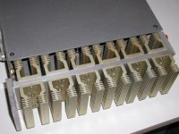
I tried to make heat sink ones too, but it was barely enough for one channel of Zen. The size is 330mm by 90mm. I used 1/2" aluminum base and attached smaller extrusions using screws and thermal grease. I bought the small sinks at $3/pc at local surplus place. It's just one alternative to building everything from scratch.
Attachments
The problem of Peters design is the height of the heatsink. I am aware of the fact that a 150mm high box isnt everybody's cup of tea, but there is no way around the fact that if you want convection cooling, the efficiency of the heatsinks is multiplied with the square of the height if the heatsink. Its a simple matter of getting the convection to work as fast as possible. If a heatsink is made high enough, the speed of the ariflow will get close to what is for fan cooled heatsinks.
Magura
Magura
I had two output devices attached in center position on a heatsink and I noticed that the heat wasn't distributed very well.
With a one piece extrusion, after a while the temperature is more or less uniform through the whole surface, but in my (made) heatsink, the area where devices were mounted was significantly warmer than the ends. I had to mount a fan on top to improve disipation. I agree that the low profile wasn't a good choice either, but the amp looked very cool this way😉
With a one piece extrusion, after a while the temperature is more or less uniform through the whole surface, but in my (made) heatsink, the area where devices were mounted was significantly warmer than the ends. I had to mount a fan on top to improve disipation. I agree that the low profile wasn't a good choice either, but the amp looked very cool this way😉
- Status
- Not open for further replies.
- Home
- Amplifiers
- Pass Labs
- DIY heatsinks