HEATSINK SUPPLIER UK
Hi, as I am looking at building the the 'X' amp........I have been looking into purchasing good heatsinks...........I am intrested in a group order (bigparsnip.....are you interested)........
please take a look at this link http://www.ablcomponents.co.uk/pages/main.htm
maybe we could buy a long length of heatsink......and have it cut to suit......
Please contact me if your interested............or post on this page🙄
Attachments

zygibajt said:and DIY heatsinks back/side
This is really too nice to be a DIY heatsink! 😀😀
Did you get them anodized?
Cheers
Andrea
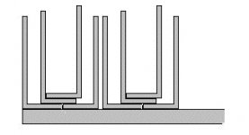
I've used a stacked approach with a 1/2" base plate and 4 levels of 1/8" sheeting separated by 1/2"x 1 1/2" x L aluminum blocks. Mine measures 7"h x 20"l x 4" thick and can dissipate obscene amounts of heat without a problem.
hey gl -
let me be the first to say, welcome to these fora. (maybe i'm not the first, i dunno.) i only wish my first post - or even most of the rest of them - had been as useful as yours. i look forward to seeing more.
/andrew - likes to learn from the folks on diyaudio
let me be the first to say, welcome to these fora. (maybe i'm not the first, i dunno.) i only wish my first post - or even most of the rest of them - had been as useful as yours. i look forward to seeing more.
/andrew - likes to learn from the folks on diyaudio
gl, Yes, there is something that just looks "correct" in your chassis and heatsink design. Do all the fins get equally hot?
Starting from you design you could quite double
the perf. with that design, still using the same squares...
Alain.
the perf. with that design, still using the same squares...
Alain.
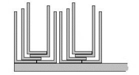
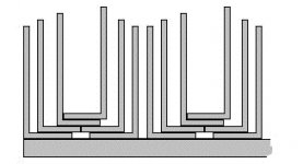
Well, I have doubled the fins, and added some more joints, I will do some calculations about this
and come back with results.
Alain.
and come back with results.
Alain.
steel filled epoxy
Hi!
Is there anybody who has experience with steel filled epoxy? It is used for to repair motorblocks and can be drilled and tapped etc. It works best on steel, aluminium and copper.
I would like to secure an alumunium L profil to the heatsinks and the epoxy could very good fill out the cavitys and scrapes,but I don't know how good heat conductor is the steel epoxy.
Could be better heat conductor the classic methode: to secure with screw and silicon paste?
BTW, If it would work it would be easy to build nice big heatsinks from L profils.....
Thanks
dont mix steel and aluminium...you will get galvanic corrosion.
Get the aluminium filled epoxy instead....there are plenty of them out there.
Magura
Get the aluminium filled epoxy instead....there are plenty of them out there.
Magura
Alternative way of making DIY heatsinks
I have another idea for an easy DIY heat sink. This one is possible to make as large as you want it with little difficulties. I'm not going to use it myself at the moment as I have what I need at the time.
But the idea is basically to copy the way the zalmann make their CPU coolers and upscale that.
How it is done is simply to take a stack of lets say 40 sheets of 0.5 mm thick copper (aluminum will do, but will not be that good, and will have to be thicker). One dimension (length) is about the same as the height of te cabinet it is built for, and the other (width) is in the range lets say 15 cm (6"). Along one side of the length there is drilled a row of holes spaced about 2-3 mm (1") apart. All the holes are drilled in the same relative position on the plates.
Then all the plates are stacked on top of each other and screwed together, preferable with a steel bar on each side with holes in the same positions. Then the loose end of the sheets are bent out and spread out evenly in spacing making a nice fan shaped as a half circle. To get a view of what they look like take a closer look at a really good picture of it at http://www.zalman.co.kr/english/product/cnps2005P.htm under CPU cooler for AMD and Pluss-Installation (almost at the top left). It was a part of a flash thing so I don't know how to copy it. You have to take a look for yourself. I recommend taking a closer look at that site (and possibly other dealing their CPU coolers) to find a good way to implement the idea. The absolute best idea is to take a trip to the closest computer store (and preferably those dealing overclocking and DIY computer equipment) and take a closer look at it yourself. I have one in one of my computers and they are EXTREMELY efficient!
Ok, the idea is so simple that it should be possible to do for anybody, and at the same time can be scaled to about ANY size. And the best thing is that all the parts needed are a suitable sheet (about 0.5 to 1 mm thick) of preferably copper or alternatively aluminum (not that easy to bend and shape).
The hardest part will probably be to mill (or grind) the face that will form the contact to the transistors. This have to preferably be totally flat and smooth to get good contact with the power transistors. But both copper and aluminum is easy to machine by hand and by spending some time there should be quite possible to make about the best DIY heat sinks possible! 😎
One other great thing about it is that it puts each fin in DIRECT contact with the heat source, and not through metal to metal transmission as in many other suggestions here.
At the power levels and densities we are dealing with here this is absolutely an advantage.
The use of this method is probably not that cost efficient for professionals. This due to the cost for making them would be a rather large part of the cost. But for DIY that is the part we want to be as large as possible. And therefore this way of doing it extra advantageous for us DIY'ers. 😀
Anders
The problem with this scheme is that to achieve even .41 degrees C/watt you need to have a fan. Most of the sinks that are required for the class A amps discussed in this forum need thermal resistances of 0.3 and better. This would require the use of at least two noisy fans.
kilowattski said:The problem with this scheme is that to achieve even .41 degrees C/watt you need to have a fan. .
Im not sure youre right there....the thermal properties of a heatsink are determined by the surface area and the mass, so all you have to do is to make the finns thick enough to carry the heat and big enough to get rid of the heat.
Ive seen very big heatsinks made by the same pricipial, like for the motor brake resistor array for building cranes.
Magura
I agree, this principle could be used to make very good heatsinks The best DIY method I've heard of I think. Of course the contact area of a single output device is about a square cm so to get direct contact, the fins would all have to taper to this width and the thickness of the stack would also have to be about 1 cm max. Well a little thicker because there is transfer between the bolted part of the fins also.
But they could taper out to say 10 cm wide, and if the fins were say 15cm long, you could spread them a lot further apart than the cpu cooler.
In this design copper would indeed work a lot better because you can pack a lot more conduction into the small contact area!
But they could taper out to say 10 cm wide, and if the fins were say 15cm long, you could spread them a lot further apart than the cpu cooler.
In this design copper would indeed work a lot better because you can pack a lot more conduction into the small contact area!
Can't stop brain, noooooo!🙄
OK maybe I get your idea better now! Just make about 20, 0.5 mm thick copper rectangles say 15 cm wide by 30 cm long. Now use bars with holes to clamp them along the 30 cm edge creating a "spine" like a bound book has. Sand down the edges by the clamp until smooth. Fan out the unclamped edges like an open book. They could be opened out to 180 degrees, allowing lot of air circulation space. Make clamping devices to attach say, 6 output devices to the "spine" of the book. These short clamp bars could be threaded into the long spine clamps and span between them, holding the output devices against the copper end layers. Or, you could probably just drill and tap into the tightly clamped "end grain" of hte copper layers.
Brilliant idea- we should call them Book Heatsinks. Done right they could look good too. Downside- copper is expensive, but I now think aluminum might be just as good as any other aluminum heatsink.
Magura,
The thermal resistance numbers I quoted are right from the Zalman website and the numbers I quoted are with a fan cooled heat sink. Sorry.
The thermal resistance numbers I quoted are right from the Zalman website and the numbers I quoted are with a fan cooled heat sink. Sorry.
- Status
- Not open for further replies.
- Home
- Amplifiers
- Pass Labs
- DIY heatsinks