Re: Copper/Aluminum bonding
There is soldering wire for aluminum (alusol) out there. I have used it, and it works. The thing special about it is it contains a flux that is strong enough to etch away the Aluminum oxide layer that forms on the surface almost instantaneous. This layer that forms so quickly is also part of the problem of welding aluminum. AC TIG or MIG is the only things that work, and does it by the AC pulses ripping away the oxide each time the polarity changes.
Ok, one warning; the flux used for aluminum is so strong that you HAVE to remove it after soldering, or it will continue to etch.
And most probably it will ruin the tip (the coating) of your soldering iron (it did to mine (it wasn't even mine, and the owner was rather ****ed on me...)). The best is to use a propane torch or some kind of contactless soldering.
I think it is possible to get the flux separately to, just have a look. Be sure to read the instructions carefully.
A shop for professional (industry) welding/soldering equipment will be able to help you here. Hard soldering with silver solder is another thing to look at.
Anders
EternaLightWith said:I tried getting aluminum heatsinks to bond to some copper sheet I had. I can't get the two to stick together. I know that aluminum is hard to bond to other metals, but this is ridiciolous. I was using flux and electronic solder. 50/50 mix. No can do.
WHat do you guys use to bond aluminum fins to copper block?
Any ideas?
David
There is soldering wire for aluminum (alusol) out there. I have used it, and it works. The thing special about it is it contains a flux that is strong enough to etch away the Aluminum oxide layer that forms on the surface almost instantaneous. This layer that forms so quickly is also part of the problem of welding aluminum. AC TIG or MIG is the only things that work, and does it by the AC pulses ripping away the oxide each time the polarity changes.
Ok, one warning; the flux used for aluminum is so strong that you HAVE to remove it after soldering, or it will continue to etch.
And most probably it will ruin the tip (the coating) of your soldering iron (it did to mine (it wasn't even mine, and the owner was rather ****ed on me...)). The best is to use a propane torch or some kind of contactless soldering.
I think it is possible to get the flux separately to, just have a look. Be sure to read the instructions carefully.
A shop for professional (industry) welding/soldering equipment will be able to help you here. Hard soldering with silver solder is another thing to look at.
Anders
Magura said:If a heatsink is made high enough, the speed of the ariflow will get close to what is for fan cooled heatsinks.
Magura
That is the reason for the form on the ML monoblocks that looked like a oil filled radiator. And also the reason those radiators are shaped the way they are.
I have one on 2kW right here, and the size of it is not that big if you think of what energies it is capable of transferring and what small delta T it has.
Came to think about it, if any of you out there would be able to except that shape (height) on your amp..... it would be about the best way to get rid of large amounts of heat at small areas.
A friend of mine was also playing with the idea of letting some kind of fluid (water is the best due to its extremely high energy/temp coefficient) be heated and thereby circulate and bring away the heat. That is a well proven technique, and should be fairly easy to do.
Hey, if all that matters is to get a cheap heatsink you could just buy one (or two for monoblocks) of those oil filled radiator ovens. Or salvage one, probably easy to get scrapped ones....
Just empty it temporarily (and keep the oil for reuse). Either cut off the bottom of it, or in some other way hack in to where the heater is, and replace it with a transistor assembly. You would probably want to make some kind of heat spreaders. One for each polarity to avoid to have to isolate the transistors electrically (at least it is impossible to use that white heat spreading paste in there... 🙂 ). A copper (or aluminum) bar would be a good idea as it could be used both for electrical supply and heat spreading. These would not have to be big. The power resistors would also only have advantage of being immersed in the oil (you could then get away with lower power rated ones since cooling of them is much more efficient, and by this get to use induction free film types).
The oil is completely electrically isolating (remember transformer oil), so there is NO problems concerning having the components immersed in the oil bath. But I would avoid capacitors in there.... (especailly electrolytics, long therm stability of rubber is dependent of oil type used.... and electrolytic chemicals in there is no good idea).
Then you connect it through the wall of the hull of the radiator by some electrically isolated but oil tight assembly (those are probably possible to buy somewhere, but you could easily make it yourself). After making sure everything works and it is tight you refill the oil. You better make sure you don't overheat the devices by testing at to high power levels before filling with oil.. 😉 . English is not my native language, so excuse the not so good explanation here......
 (This is also partly why I use so long explanations too......)
I'm sure this must be about the most cooling for the buck DIY heatsinks I can think of! And they are even capable of reasonable high power levels too, and this without the need for fans (how about that kilowattski ??? 😉 ) or any other audible means . The downside is the looks of it though..... 🙄 Then again, possible to disguise as ovens (well... they are really….. they even work 😀 ).
One more thing about it is that this is a lot less work and easier to make than the psalm book type, and don’t demand much tooling and other materials either. Come to think of it, I might try this myself sometime. The idea actually came to me while writing this post 😀 Great forum BTW….
Anders
Glad you liked this one Kilowattski 😉
Just some further thoughts on this last idea. This really made me thinking.
One thing that can make this a really efficient heatsink is something I remember reading about someone on this forum had done. I have also seen it done in CPU cooling for OC.
It is using the same mechanisms as a heatpipe, but is made simpler and cheaper. But then it is also much more scalable.
It will work on most heatsinks, but is particularly suited for the radiator oven heatsink because it is made to keep fluid tight in the first place.
The whole ting is to cover parts or the whole of the surface with a fabric that acts as a wick and gets soaked in water. When evaporating the water to the air energy is taken from the surface of the heatsink (and thus cooling it down). The efficiency can be made many times as efficient by this (especially if using moving air, but the speed doesn't need to be that high here), and the best thing is that it is possible to control it with. Either a simple mechanical thermostat that opens up a valve when it is heated to a certain temp, or an electronically controled system. The water can be spread by being let out at certain places at high locations, and the wick together with gravity will do the rest.
One other thing about this is that it is the only possible way of achieving lower temperatures than room temperature, not that we want that. And since this is also a controllable factor it is a fairly good thing to test out IMHO 🙂
One possible problem I thought of is the fact that bacteria’s and other nasty stuff like algees could possibly start to grow on the wick surfaces. This will possibly have to be taken in to account. One way to avoid it would be to make sure the surfaces aren’t wet all the time. Most bacteria’s that lives in water would then be killed. And then there is washing.....
The more I think about this idea the more I like it! Especially in the winters the air inside is way to dry anyway, so this would only help to get a better environment in the house. And then there is the availability and simplicity in getting the needed materials. And the low cost. And the possibility to actively control the temperature (fast warm up times).
Anders
I like to shake this thread back to live.
I had my inspiration of diy heatsinks from a member of this forum carpenter if i am right.
In contrary to his design my heatsinks wil not be build from aluminium but from copper sheets and copper strips.
The sheets and strips will be stacked together so they look like an ordinary heatsink.
The strips and sheets will then be solderd together.
The difficulty with this design is that the sheets and strips will drife away from eachother on the solderpaste as you clamp them before soldering.
The result is not very pretty and give an uneven place to mount the FETs.
the solution may be just stack them, and secure them without clamping.
This way soldering must be possible without the sheets floating around.
Ill report on this when tried.
Edwin
After soldering, you could lay the sink on a belt sander to even up the area where the components attach.
E. Pardaans said:
the solution may be just stack them, and secure them without clamping.
This way soldering must be possible without the sheets floating around.
why not tack-weld them?
btw, here's a heat sink formulat which is approximately correct:
A = 5630 /[ (delta T )^5/4] where A is the area in square CM. (use 873 for sq inches)
when you add fins the heat flow becomes restricted so the formula holds less and less the tighter the fins are spaced.
Variac,
Yes you are right about sanding, but the hills and valleys were so big it would take a week or more to sand them.
If you clamp the sheets they will flow.
I was not abel to stop the proces until the solder has hardened.
By then the surface was so uneven that differencies of more then 1.5mm are no ecception.
Sanding 1.5mm from a sink the size of 18 x 25cm is no option.
IMHO the only option is to optimise the "clamping" process.
If this works you have to sand the surface anyway but thats easy.
Edwin.
Jackinnj,
My sinks will be fan cooled.
The dimensions of the sinks are 18 x 25 x 7.5 cm with a baseplate of 1.5 cm.
The spacing between the sheets will be 6mm.
I think two off them will be enough for one Alepn-2 monoblock.
Edwin.
My sinks will be fan cooled.
The dimensions of the sinks are 18 x 25 x 7.5 cm with a baseplate of 1.5 cm.
The spacing between the sheets will be 6mm.
I think two off them will be enough for one Alepn-2 monoblock.
Edwin.
Capillary Action
I would think that if the surfaces are properly fluxed and enough solder present that the assembly might hold together by the action of surface tension alone. THis is common in many furnace brazing applications in industry and I think in SMP soldering.
Scott
I would think that if the surfaces are properly fluxed and enough solder present that the assembly might hold together by the action of surface tension alone. THis is common in many furnace brazing applications in industry and I think in SMP soldering.
Scott
IMO best solution for this is to clamp from all four sides...loosely clamp the edge sides first, then the flat parts and retighten all around. It'll move least that way. Make sure you first align the plates on a flat surface.When all calmped up, solder it.
Solder a flat plate to the bottom to get rid of any irregularities(air gaps between plate edges) and miximise heat transfer between plates.
Solder a flat plate to the bottom to get rid of any irregularities(air gaps between plate edges) and miximise heat transfer between plates.
Illisus,
I did align the sheets and strips on a flat surface, and it worked.
But as soon as i put pressure on the "heatsink" they start floating up because the flux is so slippery.
I have been thinking about soldering a flat plate at the bottom but have not tried it jet.
Scott,
Maybe you are right about the assambly holding together by surface tension.
I will desolder the sink i have, and try to resolder the way you said.
It will take a little while before i can try, but i will post the results.
Edwin
I have seen DIY heatsinks made from plates of copper soldered together before. It was accomplished by bolting through the plates to hold them in place before soldering.
I have constructed heatsinks myself using a variety of techniques. My favourites were the ones I made by drilling holes in a base plate and soldering thick copper wire into them. Some serious surface area is achievable that way, although more suited to forced air cooling than natural convection. Also similarly using sheets of copper soldered into grooves in the base plate.
Look to the overclocking community for ideas. There can be found many excellent custom heatsinks of all types.
Regarding Casting
<http://www.atmsite.org/contrib/Sapp/foundry/foundry.html>
On the subject of melting metal, an enjoyable page from our friends in amateur-telescope-making-land.
(this post is in reply to a couple of messages from quite a while back...)
<http://www.atmsite.org/contrib/Sapp/foundry/foundry.html>
On the subject of melting metal, an enjoyable page from our friends in amateur-telescope-making-land.
(this post is in reply to a couple of messages from quite a while back...)
Mr Evil,
Your way diy heatsinking is very nice.
Its a design i sertenly didnt think off.
Unfortunately i allready ordered the copper so have to stick by my design.
The reason for this design was that i wanted convection cooled sinks, and be able to size them to the dimensions that i need.
The dimensions of the amps keeps growing every day, until i took a life size drawing from work with me and showed it to my wife.
I must say sleeping in the garage is prety cold.😀
From that moment ill have to go with fancooling and smaller heatsinks.
The leftover copper will be used as shielding for my wooden chassis.
Edwin.
Re: Regarding Casting
This is exactly how professional foundries and tools look like.
At 18 i worked for an alloy factory for some time waiting for Navy admittance screening.
John sapp's article describes in detail how Alloy melting and pooring is done, it reads as if he has done the job himself.
Alloy molding is quite easy, heatsinks can easilly be made with sand castings.
For Dutch members :
at the time i made the big Alloy stars you see on Police Station walls, the pot containing 200 lbs of alloy was raised out of the foundry and poored in a sand mold, hard labour at 45 degrees Celsius and quite unhealthy.
I made a lot of alloy Heras Hekwerk connectors back then, those were made in steel molds sprayed with charcoal for slower solidifying.
Alloy is easilly melted because of the low melting temperature, a problem is the residu on top of the melt and foreign particles.
After the alloy is melted special tablets are put in to clean the melt. After sturring a couple in the alloy the solidified trash is taken off with a spoon.
These tablets can be bought at suppliers for the metal industry.
Those with access to a milling machine can mill swallow tails in a thick alloy plate.
Carve alloy fins at the edges with the same swallow profile, just a few microns thicker.
Place the base plate in the oven at 300 C, the fins in the deepfreezer, slide the fins in, once they have cooled the fins are fixed nearly as good as extruded heatsinks.
The easiest way to make heatsinks for me was cutting plates and welding them with Argon-Arc, TIG or MIG, i found clean 1/2" thick alloy plates at scrap yards for next to nothing.
EFHeath said:[Bhttp://www.atmsite.org/contrib/Sapp/foundry/foundry.html[/url[/B]
This is exactly how professional foundries and tools look like.
At 18 i worked for an alloy factory for some time waiting for Navy admittance screening.
John sapp's article describes in detail how Alloy melting and pooring is done, it reads as if he has done the job himself.
Alloy molding is quite easy, heatsinks can easilly be made with sand castings.
For Dutch members :
at the time i made the big Alloy stars you see on Police Station walls, the pot containing 200 lbs of alloy was raised out of the foundry and poored in a sand mold, hard labour at 45 degrees Celsius and quite unhealthy.
I made a lot of alloy Heras Hekwerk connectors back then, those were made in steel molds sprayed with charcoal for slower solidifying.
Alloy is easilly melted because of the low melting temperature, a problem is the residu on top of the melt and foreign particles.
After the alloy is melted special tablets are put in to clean the melt. After sturring a couple in the alloy the solidified trash is taken off with a spoon.
These tablets can be bought at suppliers for the metal industry.
Those with access to a milling machine can mill swallow tails in a thick alloy plate.
Carve alloy fins at the edges with the same swallow profile, just a few microns thicker.
Place the base plate in the oven at 300 C, the fins in the deepfreezer, slide the fins in, once they have cooled the fins are fixed nearly as good as extruded heatsinks.
The easiest way to make heatsinks for me was cutting plates and welding them with Argon-Arc, TIG or MIG, i found clean 1/2" thick alloy plates at scrap yards for next to nothing.
Take a blow torch and use it to reheat the solder and it will flow flat when it all melts. That is if you orient the heatsink with the solder side up when you use the torch. Get it?E. Pardaans said:Variac,
Yes you are right about sanding, but the hills and valleys were so big it would take a week or more to sand them.
If you clamp the sheets they will flow.
I was not abel to stop the proces until the solder has hardened.
By then the surface was so uneven that differencies of more then 1.5mm are no ecception.
Sanding 1.5mm from a sink the size of 18 x 25cm is no option.
IMHO the only option is to optimise the "clamping" process.
If this works you have to sand the surface anyway but thats easy.
Edwin.
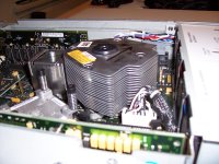
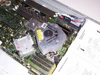
I've been reading this thread and figured I would show a few pictures of a heatsink that I found in a server at work. It falls into the same idea as many of the proposed DIY heatsink designs talked about already.
There is a single thick post that connects to the heat source with the fins made of thin metal and just stacked with a slight gap in between them.
This design does not use any forced convection (no fans) but I'm also not sure about the particular heat generated by the processor it is attached to.
Sorry for the large file size. The pictures were already decreased in size and quality dramatically.
Attachments
It's not how you solder but how you heat it!!
When you are trying to solder up a large item such as a DIY heat sink here is a small tip. Get this first. A plate of steel or even aluminum that is about 1/2" or 12mm approximate thickness. Think about it a a big enough hot plate. Next you need alot of evenly distributed heat. Fortunately most of us have stoves. If you are on the right set of train tracks now you will figure out that the temperature is adjustable on a gas or electric stove. How hot do you want??? Not enough to melt the solder but enough to almost melt it. You should still need to apply localised heat with a torch to actually do the melting. If you do this setup correctly there will be a minimum amount of maching needed after because all the pieces will rest flat against the plate and behave themselves. One note when you are finished with your soldering turn off the heat on the stove and let it cool slowly. Much better that having failed solder joints.
Mark
- Status
- Not open for further replies.
- Home
- Amplifiers
- Pass Labs
- DIY heatsinks