Will you post your spice file?
I removed D5 (the one that connects directly to the output) and that solved the problem, with no apparent problems from removing it. I don't think it was needed.
I removed D5 (the one that connects directly to the output) and that solved the problem, with no apparent problems from removing it. I don't think it was needed.
The peaks look like simulation errors,they are very short and they look much different on different fets
What is the purpose of the diode that connects to the output (D5)? I took it out and my circuit simulates better, and no more current spikes!
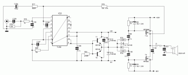
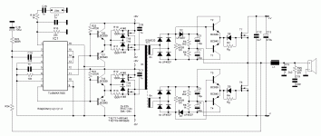
Few new (better) designs from me
All schematics is tested.(second schematic tried directly on 310V line,with IRF740)
Answer to Q about D5:
It's used to remove negative voltage on upper fet.
All schematics is tested.(second schematic tried directly on 310V line,with IRF740)
Answer to Q about D5:
It's used to remove negative voltage on upper fet.
Attachments


Last edited:
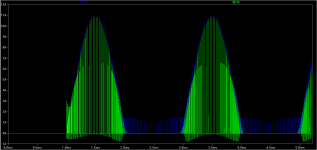
Yes,there is short current peaks because lower fet have small delay (in order to form dead time)Here is a screenshot of the high current thru diodes (output unclipped, 40v P-P)
Surprisingly, there is very little cross- conduction on the output MOSFETS though🙂
I can say what I thought,
For a 'correct' dead time, you need need a digital circuit, as they did here with gates A1,A2 :
http://geekcircuits.com/wp-content/uploads/2010/07/tl494-class-d-power-amp1.png
Because the signal is too weak, after these gates, you need a MOSFET driver (IR2010).
The price of IR2010 plus the remaining components It's almost as the price of IRS2092.(SMD version of IRS is cheaper). (Using this IRS, your risk of error is less)
I already ordered the IRS.
Still looking for very cheap variant class D amplifier (price of TL494 is less than SG3525)
For "correct" dead time we can use RD network too.
Before I try,I think same as you.
-Yes-And irfz48 it will serve?
-I will use it for listen some music at home not hi-fi.
-Is this possible with a smps at 56Vcc made from a ATX power supply conversion?
-Thank you and have a good weekend.
-You are my man 🙂
-Why not?
-You too
Yes,you can use it,or you can use E25 or E33 with gap instead.Hi. Is this core (DTMSS-27/0.033/20V from tme) usable into schematic from post 268?
The output capacitors can be normal capacitors or it must be Low ESR?
I use classic capacitors,not LOW ESR,but if you have it,use it.
Acca,
Thank you for sharing your creative and unique designs with us🙂
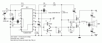
I have simulated post #275 in LT Spice. It works, but
I am concerned with the VERY HIGH current through diodes D4 and D5. Is this normal? Do the diodes in your prototype get hot or fail? I simulated them as 1N4148.
It's just a little warm,I use BA159.It don't fail 🙂
hi acca i have irfb4227 with me and i wanted to use them in parallel at +/-80vlts at 1 ohm load . which circuit will i use with parallel fets at that voltage?
Hi,for that power I recommend second schematic because it have isolated,and +/- drive.For high power it's necessary,because current spike can activate wrong output fet,and BOOM.
But It don't use split rails,you can use it with single 160V rail and 10.000u cap's or higher for output.You don't need capacitors in PSU,this cap's will be used for it.Yesterday I tried to use split rails,and it only complicates design without high upgrade.And with +/- you need DC protection.I don't see isolated and +/- gate drive for class D.This is much better than sh** IR2110,because it's very "sensitive" to fail.For 2110 you must take high care about PCB,on my design you don't 🙂
Gate drive is independent from each other.
For output inductor use E33 with 1.5mm gap between core halfs and wind 30-40 turns of thick wire or Litz wire.
If you like to parallel fet's,each fet should have their own 220R+diode in gate.
I use this amp for drive 100V line in one market and it works ok. (Supply voltage is 310V direct rectified line,fet's IRFP460 with 100R in gate,freq. is 60kHz,and I don't have input transformer because isolation provided with GDT,oscillator is driven from small SMPS 12V.I don't see that any class D amp is driven directly on 310V 🙂 )
Last edited:
This is especially with fakes 🙂This is much better than sh** IR2110,because it's very "sensitive" to fail.
Acca,
Thank you for sharing your creative and unique designs with us🙂
I have simulated post #275 in LT Spice. It works, but
I am concerned with the VERY HIGH current through diodes D4 and D5. Is this normal? Do the diodes in your prototype get hot or fail? I simulated them as 1N4148.
Hi,I didn't tested any of my class D or SMPS in any program,I use head and test in my primitive "lab" 🙂
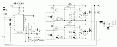
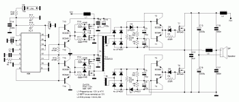
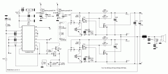
Hello all,I tested this design with opto and works better than IR2110.And have separated isolated gate drive.
See schematic.It work on split supply.+/- 8V for 494 can be obtained with zener and resistor from +/- PSU rails.Current needed is about 60mA for each voltage.
0V_1 and 12V_1 use one 12V psu,that is separated from other voltages (separated secondary).0V_2 and 12V_2 too.
If you like to use one secondary,you can use bootstrap for upper voltage,like IR2110 but I don't recommend this.Great sound,no noise and hum.Very simple and powerfull,even on small voltages 🙂
Output can use any from +/-12 to +/-120V.I'll try on +/-125V and see what's happening 🙂
Attachments
Last edited:
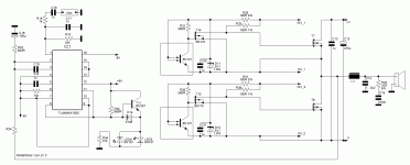
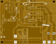
PCB and final version:
Bootstrap circuit in hatched rectangle is used only for test's.For final use,you should use two separated 12-15V supplies.
Bootstrap circuit in hatched rectangle is used only for test's.For final use,you should use two separated 12-15V supplies.
Attachments
Last edited:
- Status
- Not open for further replies.
- Home
- Amplifiers
- Class D
- DIY Good Class D amplifier