

I am getting close to finishing my layout for a 2 channel pcb for this project and have a couple questions:
If using the LSK389 which grade would be best?
Would 50V Nichicon Muse bipolar electrolytic caps (the green ones) be ok for C1,C2,C3?
I have added a set of switches for variable gain, jumper for balanced/single ended input and pads for 2x J113, 1x 2SK170 or 1x LSK389 (SOIC8 package), any additional features tweaks that I should add to the board?
Thanks!

I would not use electrolytic caps here. I'm using WIMA MKP4 polypro, but they're relatively gigantic and expensive. The mylar/PET WIMAs or their polyester equiv. like in original BOM should be fine.
Others will advise on grade of transistor, but you might need C to get 8-9mA through Q4.
Others will advise on grade of transistor, but you might need C to get 8-9mA through Q4.
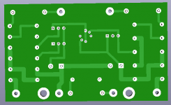
Also, I don't want to critique your board--it's super neat and tidy, which is great!! But I'm trying to minimize my gate trace lengths. I did not do a great job of that on my previous PCBs and they work fine, so maybe it's not critical for these applications. But the low gate currents (High Z) generally should not be allowed to flirt with noise/leakage. Once those traces reach the junction of the two connecting resistors, you're probably okay.
P.S. It looks like your channel 2 diff pr. gates are tied together (Q201/202). (?)
P.S. It looks like your channel 2 diff pr. gates are tied together (Q201/202). (?)
Last edited:
Aleph5 Thanks for catching the error at Q201/Q202 gates! Also thanks for the sharing your test results in post 435 they were really helpful. Do you think it would be good for me to add a location to include a feedback capacitor on the KSA992 as you mentioned in that post? Does the right hand side look better regarding the length of the gate traces now? (If so I will update the left side to match).
Thanks again!

Thanks again!
I like those gate traces much better! I don't think I'll need a cap across the KSA992, and if others have been fine without one, it might be a wasted effort. If I can fairly easily fit it in, OTOH, I will probably go with it just to keep options open. So ¯\(ツ)/¯ . Your call, depending on time, effort, and space.
Happy to hear I'm helping. 🙂
Happy to hear I'm helping. 🙂
Neat little board, csample! With your input and output caps close to the board edge, if you made pads in parallel, other caps could be used too, even off-board.
Q105 and Q205 are the 'donkey' (workhorse?) BJT right? Does it have the pads too close? Is there ever a chance to put in a bigger one, or space for a small heat sink, for the greedy boiz..??
Doesn't this depend on what is the Idss of the J113 that biases them? So you want the lower one (J113? or also LSK389?) to have lower Idss than the upper jfet? I really should not be the one to rely on for this....If using the LSK389 which grade would be best?
In an email from Nelson he says the Idss is not that critical - B grade will be fine, which is the same as BL grade for original Toshiba devices, I asked him that as I have some 2SK170BL to use for Q1 and Q2 in his circuit. Also it would be great if you could fit it in to allow the use of the Toshiba 2SK389 7 pin package, for those lucky enough to still have some of these - just a thought. Nice work on the pcb so far.
I think there is space for a clip on TO-92 heatsink if needed, but I don't really intend to push the limits so hopefully it won't be needed.Q105 and Q205 are the 'donkey' (workhorse?) BJT right? Does it have the pads too close? Is there ever a chance to put in a bigger one, or space for a small heat sink, for the greedy boiz..??
Definitely a higher probability of success and a cheaper way to go. I wanted to use the LSK389 and I like to layout boards.I would just copy Mr.Pass' PCB design.
Doing an A/B test with the Nichicon Muse bi-polar and some off board film capacitors could be a good way to go, but I would really like to keep everything on the board to keep the layout in the chassis clean.Neat little board, csample! With your input and output caps close to the board edge, if you made pads in parallel, other caps could be used too, even off-board.
gary s - Thank you for sharing the information from Nelson. The B grade LSK389 is the only one in stock at Mouser so that is what it will be. I don't feel that there is space to add a 4th transistor option for the Q1/Q2 pair so I will leave that challenge for someone else.
Any other thoughts on using the Nichicon Muse bi-polar capacitors for C1,C2,C3? They are used in other well regarded amps like the M2X and really save a lot of space on the board. If they are not good I don't want to use them, but my go to film capacitor is the Clarity Cap CSA and that would double the size of the board.
Thanks everyone for all your thoughts and suggestions! Much appreciated!
They (Muse) are about the best sounding 'electrolytic' there is, but I would want film caps if only 3uF is needed, even if I had to use Wima MKS...
Don't forget a pad for the LED resistor!
Best to let Zen Mod have a look before sending off!
Don't forget a pad for the LED resistor!
Best to let Zen Mod have a look before sending off!
You just know someone will plug in a pair of IEMs. How about a set of parallel pads for the BJT also? Since 'parallel' is the repeating theme...I think there is space for a clip on TO-92 heatsink if needed, but I don't really intend to push the limits so hopefully it won't be needed.
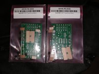
My pair of boards arrived today. I wasn't planning on building them but an open evening and rummage in the parts box made it look like it might be worth the effort.
I cheated a bit and used 2.2uf film caps, since that was all i had. I got lucky with the rest of the parts in that they were on hand. No fancy stuff, just every day caps and resistors. Seemed appropriate to stay with the DIY crowd wants it cheap and easy theme.
Both boards came together in under two hours with not much effort. I checked each component with my parts tester before instilling. It helped with the orientation of Q1-Q5 since you need to pay attention to the correct GSD pinout placement. (The part tester told me which leg was G,S or D)
I built the single rail, SE input version. I had a an old chassis that i repurposed into a preamp using the H2 board and an SMPS +24V power supply. I removed the H2 board and subbed in the FE 2022 boards. My wiring is all over the place but I've learned to get it working first and clean up those details another time.
It sounds fabulous. It's beyond belief that anything I purchased for $20+ could sound this good. And be so easy to build.
I can't wait to see what other uses we can come up with for the latest Papablock.
As always, thank you to Nelson for his genius and generosity.
I LOVE seeing projects where parts on hand get used. Fantastic!
Attenuator output ground attaches to V-, not -IN.
-IN jumper to V-.
Yes, the V- pad gets a lot of wires to it.
Attenuator output ground attaches to V-, not -IN.
-IN jumper to V-.
Yes, the V- pad gets a lot of wires to it.
Danged Greedy B-words snapping up all the DIY FE 2022 Kits from the store in under 12 hours. 😳
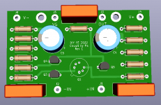
So I went ahead and laid out a version for myself so as to use some LSK389's I already have on-hand. Gives me more practice using KiCAD.
I just used Pa's PCB component arrangement, plopped the LSK389 in the middle and routed to my liking.
I may be a Copy Cat, but at least I'm not a Greedy B-word.
So I went ahead and laid out a version for myself so as to use some LSK389's I already have on-hand. Gives me more practice using KiCAD.
I just used Pa's PCB component arrangement, plopped the LSK389 in the middle and routed to my liking.
I may be a Copy Cat, but at least I'm not a Greedy B-word.
Attachments
“Boyz”
It’s “Greedy Boyz”
No need to make people think you are saying something else, because of course, you aren’t….
I LOVE the idea of using K389.
A couple suggestions for the PCB,
-Add VG connection near signal input.
-Make capacitor lead spacing and 27.5mm, that’s the “normal” size box capacitor for this value. A few narrower pard inside it are always easy to add.
-Double up the pads on V-, many connections happen there with a single supply.
Last edited:
- Home
- Amplifiers
- Pass Labs
- DIY Front End 2022