I'm reading Small Signal Audio Design, 3e, and chapter 1 lays out 3 rules for Gain Structures, among them, "2. Don't attenuate then amplify". But perhaps the volume pot in this case is not part of the Gain Structure in that context.proper place for volpot is before gain stage
Is it common that Preamplifiers use a simple potentiometer on the front end as you suggest, @Zen Mod ? I mean, the AKSA-Lender is set up this way, but I guess I assumed that in a commercially-built amplifier the volume knob was connected to control some variable gain circuit., so that the input impedance stays fixed regardless of volume.
Kind regards,
Drew
Sounds like a fantastic use..Can I use it as a quality converter with minimal gain from balanced to unbalanced?

@dliscomb
what you're going to build, exactly?
if DIY FE 2022, which is main star of this thread, used as preamplifier........ then let's stay at that and talk about that
what you're going to build, exactly?
if DIY FE 2022, which is main star of this thread, used as preamplifier........ then let's stay at that and talk about that
Hi,
Could DIY FE 2022 be used in such a topology (without C3 and with mixed feedback)?
https://www.diyaudio.com/community/...former-for-no-coupling-caps-amplifier.382243/
I have a 400VA 2x32V transformer, a set of appropriate lateral mosfets.
Regards,
Nicolas
Could DIY FE 2022 be used in such a topology (without C3 and with mixed feedback)?
https://www.diyaudio.com/community/...former-for-no-coupling-caps-amplifier.382243/
I have a 400VA 2x32V transformer, a set of appropriate lateral mosfets.
Regards,
Nicolas
Hi
2 questions i would have regarding the Front End 2022:
1] Regarding putting a volume potentiometer in front of it, for balanced inputs, is it OK to use an ALPS RK27 10k "4 gangs" / "4 ways" like this one https://www.audiophonics.fr/en/pote...ys-potentiometer-d-shaft-10-kohm-p-15801.html and wire it like described here http://www.dact.com/html/wiring_a_balanced_stereo_passi.html
I think it should be correct, but i would like to check with experienced members of the forum.
2] Just a slight "freak-out" / "did i use the right capacitor" ?
C4 & C5 are 1000uF rated 25v in the BOM
In the original schematic, with +/-24V, they will see 23.5V each (Qspice "FrontEnd2022_Original_Schematic_Article"). It is a bit borderline but OK.
Doing the changes for Single Ended Power Supplier +36V, (Qspice "FrontEnd2022_SE_36v-PSU_Schematic"), Voltage @N04 is 35.5v, voltage difference is V(N04)-V(Vg) @c4 roughly 17.75Volts [V(N04) roughly 35.5v, V(vg) 17.75v]
= I was initially (prior to the calculation) thinking that 25V specs capacitor would be an issue with +36V single ended power supply, but it will not be a problem...if i am correct with the circuit simulation.
pdf with schematics in QSpice and voltage graph attached "QSpice-Schematics-and-Graphs"
A. is it correct?
B. if correct, wouldn't it be better to have higher rated C4/C5 capacitors in the BOM, just out of caution / if somebody pushes the power supply voltage?
(some appears to have powered the Front End with +62V, Ben Mah Post #1299 https://www.diyaudio.com/community/threads/diy-front-end-2022.394339/post-7516867) User Vix is having 50V caps in the post just above (1298))
I guess it is DIY and real life experimentation is important...
Thanks in advance for any insight.
ps: QSpice models attached, as well as *.txt files for J113 N Fet & SA992 to run them.
ps2: in the article's picture of the board, the caps are rated 50V 😏
Attachments
-
QSpice-Schematics-and-Graphs.pdf1,000.6 KB · Views: 185
-
2SA992.txt302 bytes · Views: 95
-
FrontEnd2022_Original_Schematic_Article.qsch19.9 KB · Views: 126
-
FrontEnd2022_SE_36v-PSU_Schematic.qsch18.7 KB · Views: 120
-
FrontEnd2022_SE_36v-PSU_SE_Input_Schematic.qsch18.8 KB · Views: 109
-
J113.txt214 bytes · Views: 107
Last edited:
yes, i've done it - see post #514 in Slob discussion threadis it OK to use an ALPS RK27 10k "4 gangs"
lolo6990,
Yes I have 62V per channel and I used 35V capacitors. If you look at the FE schematic you will see that each capacitor has a 10k resistor in parallel. That divides the voltage evenly between the two capacitors. So whether the power supply is bipolar or unipolar, the total voltage is split between the two capacitors. In my case each capacitor sees 31V.
Yes I have 62V per channel and I used 35V capacitors. If you look at the FE schematic you will see that each capacitor has a 10k resistor in parallel. That divides the voltage evenly between the two capacitors. So whether the power supply is bipolar or unipolar, the total voltage is split between the two capacitors. In my case each capacitor sees 31V.
@Zen Mod , yes, "DIY FE 2022 ... used as preamplifier", that's what I was trying to understand.
I had ASSUMED that was the purpose of this "front end", however my ongoing education now leads me to understand that this project was intended to be a voltage gain stage that would sit inside a power amplifier chassis, like a MoFo or M2X.
Kind regards,
Drew
I had ASSUMED that was the purpose of this "front end", however my ongoing education now leads me to understand that this project was intended to be a voltage gain stage that would sit inside a power amplifier chassis, like a MoFo or M2X.
Kind regards,
Drew
it can be used as standalone line stage, with lower or higher voltage gain
anyhow, wherever used, if volume pot is implemented , its place and position is in front of this gain stage
only when gain stage is made from start deliberately to have some sort of either variable attenuation or variable gain setting (depending how you look at it), potentiometer can be placed differently
example - Aleph P, which had resistor matrix ( switched with relays and logic), functioning as Volume control, but actually being variable load for stage, thus varying gain
ppl later did try to build it more or less successfully, taking various approaches to have Vol Pot - some did use fixed gain for stage, with standard VolPot in front, some did use relatively low resistance VolPots at output, some used relatively low resistance pot at output, arranged as variable resistor
probably just last choice was best one, for simplest DIY
Like this ?Hi,
Could DIY FE 2022 be used in such a topology (without C3 and with mixed feedback)?
https://www.diyaudio.com/community/...former-for-no-coupling-caps-amplifier.382243/
I have a 400VA 2x32V transformer, a set of appropriate lateral mosfets.
Regards,
Nicolas
Attachments


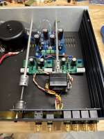
Finally whipped together the FE2022 as a preamp into a chassis already in my stash.
Used @Ben Mah's psu board set up as a +/-25V bipolar supply.
Sockets installed at R3 and R4 for easy gain adjustment to match different amplifier needs.
C3 is physically installed, but a jumper is soldered under the board to bypass the cap.
Wow!
These gems have been sitting in my drawer since they were released, I should have built them sooner. Impressive sound for such a simple low parts count build. Now that I've had some listening time, this pre deserves more attention to build details.
Thank you for sharing the FE2022 Nelson!
🍷🍷🍷
Attachments
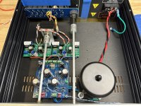
Nice build, and I agree that it is a great preamp.
I hope your transformer enclosure does not create a shorted turn.
I hope your transformer enclosure does not create a shorted turn.
Very nice build Vunce - as usual for you. If you are using the J113 fets at the input pair, then a pair of matched 2SK170BL's will be so much better, like chalk and cheese on my build. Still my pre amp of choice - as you say, so simple.
It's a steel center bolt but they give you a plastic shoulder washer and plastic "acorn" nut that avoids the problem.I hope your transformer enclosure does not create a shorted turn.
- Home
- Amplifiers
- Pass Labs
- DIY Front End 2022