No plans yet, just a piece of MDF to start with.You always make such beautiful chassis’, if I remember correctly. So looking forward to future ones 🙂

I've got plans so have just ordered a second kit - sorry to join the greedy boyz!
Looking through my stash I've located a matched quad of Toshiba K17 fets that I purchased from Spencer a while back, the packaging says 8.3mA.
My plan is to use these as a balanced to SE line-amp stage in front of an Intact Audio (Slagle) autoformer volume control - that will drive my THF-51S version of Ben Mah's Fokin project.
My plan is to use these as a balanced to SE line-amp stage in front of an Intact Audio (Slagle) autoformer volume control - that will drive my THF-51S version of Ben Mah's Fokin project.

Sorry all, I have a couple of newbie questions. After building an M2x and Aleph J I figured I would take a crack at building a preamp and since this board has a balanced connection capabilities I figured I would build it with the Aleph J in mind. Here are my questions:
1. What would be a good gain choice for the Aleph J? I know you usually want a 10-1 Power Amp to Pre Amp impedance ratio, but I don't have the full understanding on how this works with the Gain choice here.
2. What is the best method to power this thing? I know that a SMPS would be the easiest, however I am leaning towards going linear. Was looking to pickup a VPT48-520 transformer however I am a little unclear on the best Power Supply board to use. I know the Universal would work but I am guessing that it will be overkill for this application. I picked up a Super Regulator off the DIY store and although it was not the reason I picked it up, could possibly use this to power the boards?
3. This goes along with question 2, Initially I am looking at using one input and an Alps potentiometer that I have laying around. Eventually I am thinking of using an Arduino to control volume and control the input switching. would a multiple voltage power supplier be better(+-48/+12, or could I use the 48V and power supply listed above and drop the voltage down after the Power Supply to support the Arduino?
Sorry for the long post, and thanks in advance for any assistance.
Unless the Alps potentiometer you want to use is a quad unit, you may find it simpler to build a single-ended preamp. This one is a good choice. Just ground the minus input. The output is already single-ended.
Gain depends on speakers, etc, but generally I find that 6 to 10 dB works well most of the time for today's sources.
For power supply, you may want to read Papa's articles where he describes regulated supplies specifically for preamps. (A75 front end, and Balanced Zen Line Stage come to mind). I am unsure if you will hear a difference compared to a SMPS, but there is a certain satisfaction in incorporating the power supply into the box - I find.
If you later want to add an Arduino, the simplest is to add another transformer just for this digital circuit. This isolates the analog and digital supplies better.
Hope this helps,
Pierre
I built something similar to what you are asking about @jpeterson1 but not balanced out. I believe you need another pair of boards
I have all my sources now on a shelf I converted from a closet and had to run 15 foot xlr balanced cables to my preamp/amps.
I have a BBA3 with F4 monoblocks but wanted a simple option for experimenting with other single ended amps.
I built a Front end kit with VRDN, some Wima caps from @poseidonsvoice, a quad alps pot, 2 inputs, 2 outputs, and gain switches to change from 10 db to 20db. I mainly wanted to experiment with the Mofo and the F4s I have but having the 10db switch allows me to try other amps.
It sounds lovely.
Attachments
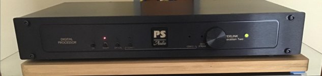
Finally completed my V0R0 DIY Front End preamp!
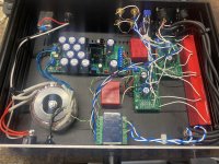
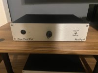
I planned on using this preamp in my living room, so I thought the case should look a bit better than an aluminum box. I had an old PS Audio Superlink DAC in the cupboard that I elected to repurposed for the job. The biggest challenge to using this chassis was to reconfigure the capacitive-touch buttons for control of power and input switching. Since I was not able to find a ready-made interface to these buttons, I decided to go old-school and use pushbutton switches. I was able to use the existing holes in the front panel for the switches, indicator lights and volume control. The old lettering on the front panel is a bit distracting, but I am going to live with it for now.
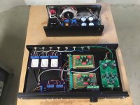
Previously, I had built a line-level preamp with removable circuit cards so I could compare different op amps (the AD845 wired for unity gain turned out to be my favorite at the time), so I decided to put the DIY FE on the same card so I could inter-change them for making comparisons. Since single ended and unity gain worked for me previously, I decided to stay with that topology. I decided to socket mount all the transistors and the gain setting resistors so experimenting with alternate arrangements would be easier. I elected to use a regulated +/- 20V for power, 2.2 µF input and output capacitors, and an Alps 50K input potentiometer.
I used relay input switching in my previous design, and since I still had some relays available, I decided to go that route again. Also common with the previous design is the external unregulated power supply.
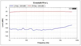
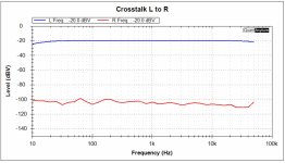
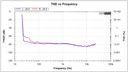
Measurements on this unit look very good. This is, by far, the quietest preamp I have ever had in my system. The residual noise and distortion areabout as low as I can measure. The distortion level and profile are the same as the QA401. Some of the measurements are shown in the attachments. One interesting result is the crosstalk measurements, the right to left is not as good as the left to right. I might be able to fix that by re-routing some wires, but I wonder if it is worth it, considering that I am working with such low levels.
So, how does it sound? Before I tried to make that assessment, I measured the voltage of a 1KHz test tone at the speaker for each preamp. For the DIY FE preamp, with the volume set at maximum, it was 1.46Vrms. For the preamp I have been using the past few years, a tubed Assemblage L-1, with the volume set at the level I normally use, I measured 1.67Vrms. If I did my math correctly, that 0.2V amounted to about a 6dB SPL difference with my 4Ω speakers with an 86dB / 2.83V sensitivity. That’s a larger difference than I expected, but I went ahead and listened to a few tracks before I made any volume adjustments. On 8 out of 11 tracks I compared, the DIY FE preamp sounded just as loud as the Assemblage preamp. That 6 dB difference should make the DIY FE preamp sound about half as loud, but that is not what I found. Not sure what that means, if anything. Maybe someone can offer some ideas? But what I did notice was that music through the DIY FE preamp sounded crisper, with greater clarity – using the visual analogy – it is like a thin scrim has been removed. All told, I could not be more pleased with the look and sound of this preamp.
Thanks Mr. Pass.
Cheers,
ceulrich
I planned on using this preamp in my living room, so I thought the case should look a bit better than an aluminum box. I had an old PS Audio Superlink DAC in the cupboard that I elected to repurposed for the job. The biggest challenge to using this chassis was to reconfigure the capacitive-touch buttons for control of power and input switching. Since I was not able to find a ready-made interface to these buttons, I decided to go old-school and use pushbutton switches. I was able to use the existing holes in the front panel for the switches, indicator lights and volume control. The old lettering on the front panel is a bit distracting, but I am going to live with it for now.
Previously, I had built a line-level preamp with removable circuit cards so I could compare different op amps (the AD845 wired for unity gain turned out to be my favorite at the time), so I decided to put the DIY FE on the same card so I could inter-change them for making comparisons. Since single ended and unity gain worked for me previously, I decided to stay with that topology. I decided to socket mount all the transistors and the gain setting resistors so experimenting with alternate arrangements would be easier. I elected to use a regulated +/- 20V for power, 2.2 µF input and output capacitors, and an Alps 50K input potentiometer.
I used relay input switching in my previous design, and since I still had some relays available, I decided to go that route again. Also common with the previous design is the external unregulated power supply.
Measurements on this unit look very good. This is, by far, the quietest preamp I have ever had in my system. The residual noise and distortion areabout as low as I can measure. The distortion level and profile are the same as the QA401. Some of the measurements are shown in the attachments. One interesting result is the crosstalk measurements, the right to left is not as good as the left to right. I might be able to fix that by re-routing some wires, but I wonder if it is worth it, considering that I am working with such low levels.
So, how does it sound? Before I tried to make that assessment, I measured the voltage of a 1KHz test tone at the speaker for each preamp. For the DIY FE preamp, with the volume set at maximum, it was 1.46Vrms. For the preamp I have been using the past few years, a tubed Assemblage L-1, with the volume set at the level I normally use, I measured 1.67Vrms. If I did my math correctly, that 0.2V amounted to about a 6dB SPL difference with my 4Ω speakers with an 86dB / 2.83V sensitivity. That’s a larger difference than I expected, but I went ahead and listened to a few tracks before I made any volume adjustments. On 8 out of 11 tracks I compared, the DIY FE preamp sounded just as loud as the Assemblage preamp. That 6 dB difference should make the DIY FE preamp sound about half as loud, but that is not what I found. Not sure what that means, if anything. Maybe someone can offer some ideas? But what I did notice was that music through the DIY FE preamp sounded crisper, with greater clarity – using the visual analogy – it is like a thin scrim has been removed. All told, I could not be more pleased with the look and sound of this preamp.
Thanks Mr. Pass.
Cheers,
ceulrich
Attachments
-
 Crosstalk R to L.jpg114.7 KB · Views: 490
 -
 Crosstalk L to R.jpg96.6 KB · Views: 245
 -
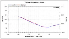 THD vs Output Amplitude.jpg92.9 KB · Views: 221
 -
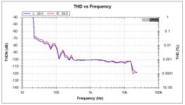 THD vs Frequency.jpg103.9 KB · Views: 247
 -
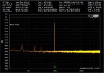 Distortion Spectrum.jpg189.6 KB · Views: 236
 -
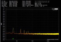 Distortion Spectrum - Shorted Input.jpg172.3 KB · Views: 280
 -
 Front Panel.jpg107.1 KB · Views: 492
 -
 Completed Unit & PS.jpeg418.9 KB · Views: 527
The noise and channel separation may be improved if each signal wire is tightly twisted together with their ground wire from input RCA to board input and from board output to output RCA . Twisted pairs drastically reduce the wires' ability to behave as attennae, to broadcast and receive electromagnetic radiation (signal and noise).
The THD versus frequency plot looks not so good below about 300Hz. Build issue or testing issue?
The THD versus frequency plot looks not so good below about 300Hz. Build issue or testing issue?
Hello Dennis, thanks for the reply. Yes, I did that same calculation, but I thought I needed to compare the sound pressure level produced by the two voltages, and not the voltages themselves. Maybe that logic is not, correct? If it is correct, then, I thought the way to do that conversion is using the sensitivity factor for speaker, and then did I do the calculations correctly?
Hello Ben Mah, thanks for the reply. Your point on twisted pairs is well taken. The wire connecting the input switching to the volume control is a 3-pair cable, not sure how the twisting goes, so that may be a problem I can fix. The wire from the volume control to the amp input is miniature coax. I agree, the THD below 300Hz does not look good. That data was collected with the QA401 20-dB attenuator turned OFF. I have other data that looks a bit better (see attachment) that was taken with the 20dB attenuator turned ON. At the time, I assumed the difference was just due to the difference in sensitivity. Comparing the two now, I’m not so sure. Build issue or testing issue? I will work on it.
Cheers,
ceulrich
Attachments
The coax and 3-pair cables have their conductors side by side or twisted together internally so they should not be an issue.
The main issue is the separation of the input signal wires from their ground returns and the grounds from the RCAs connected directly to the power supply. The ground wire from each RCA should be twisted together with the signal wire and taken to the selector. The L and R outputs from the preamp board should each be twisted with a wire from the ground on the preamp board and taken to the RCA outs.
Twisted pair information, including an interesting video
I do not have a QA401 so I have no idea what is going on there. I suggest you use a meter and monitor the AC input voltage and AC output voltage of the preamp when testing to confirm levels. Did you load the output with a 10k resistor for the test? And was the preamp output 1Vrms?
I use REW and a Focusrite USB audio interface along with a diy voltage divider (Akitika) for my tests so I control the levels and use a meter at the preamp output to measure the output voltage.
I put the unit back on the test bench and re-ran the distortion measurements. THD vs frequency came out much better (see attachment), THD vs output was the same.
So, I guess the problem was a testing issue.
Ben Mah,I understand what you are saying about the wiring topology from the input connector to the selector switches, and that this is commonly considered the best approach. But, from my research, in practice, many designers seem to do what I did. Look at the picture of 6L6’s construction on this forum (sorry I could not quickly find the post #). In addition, with the distance being only about 7.5”, I thought it a reasonable compromise.
The wire from the amplifier to the output connector is another matter. 6L6 uses coax, and I thought about that quite a bit. I finally decided to just use a wire, and if I had interference problems or noise, I could easily change it. In fact, the differences in crosstalk between L>R and R>L may be due to not shielding or twisting those wires. But with crosstalk around -100 dB, does it make any real difference?
I appreciate your comments, any thoughts about the calculations for sound pressure levels?
Cheers,
ceulrich
Attachments

Twisted wires and minimum loop areas are based on science. But if you are happy, then all is good. 🙂
As for the calculations, what Dennis said.
As for the calculations, what Dennis said.
I have front end 2022 kit waiting to be built and also have a F4 finished soon. Is it OK to mount the front end board at the and of the amplifier board as shown in the photo and use the F4 +/- 24v power supply to power the front end boards as well?

As I understand it, the circuit is essentially single ended. Is there any advantage to going for a split positive and negative supply?
- Home
- Amplifiers
- Pass Labs
- DIY Front End 2022