With anodized/painted chassis pieces, make sure that all of the pieces behave as one electrically.

I am stumped... built the boards, attached them to a known good PSU and got no signal through. I must have misunderstood something, somewhere.
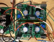
All connections are fine, continuity tested. What I put on the newer boards was the C6, the pot (P1) instead of the R6. I used R13 though it seemed unnecessary and left off R14 - I connected nothing to GF port.
It is single ended input so -IN is connected to VG, VG is connected to ground. V+ gets +15VDC, V- gets -14.9VDC. Out goes to Out except I have not signal out.
Anyone have an idea of what I must have done wrong???
Attachments

Did you adjust the pot to zero the output offset?
Are your signal input and output grounds connected to VG?
Are your signal input and output grounds connected to VG?
Good questions. There IS no output so there is no offset. Indeed it measures as 0
My guess is that there is a grounding issue but there is only ONE ground in the whole Schematic: VG. -IN goes to that VG and VG goes to the PSU ground which goes to an actual plate of aluminum. I have continuity from VG to the aluminum plate.
My guess is that there is a grounding issue but there is only ONE ground in the whole Schematic: VG. -IN goes to that VG and VG goes to the PSU ground which goes to an actual plate of aluminum. I have continuity from VG to the aluminum plate.
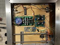
Please post a picture showing everything.
Also please tidy up the wires by grouping them together so it is easier to see what is going on. I.E. twist V+ V- G together, IN+ and IN G together, and OUT+ and OUT G together.
Also please tidy up the wires by grouping them together so it is easier to see what is going on. I.E. twist V+ V- G together, IN+ and IN G together, and OUT+ and OUT G together.
Thank you for following me on my thought journey. As I contemplated how to do what you've asked it occurred to me that I may have made assumptions about how to feed this circuit. I KNOW it is connected correctly to PSU but I am unsure about how to volume control the input.
Is it just like normal: center of RCA to center terminal of log pot, one terminal on either side goes to ground and the other goes to +IN?
Is it just like normal: center of RCA to center terminal of log pot, one terminal on either side goes to ground and the other goes to +IN?
I would want to see the voltage across R7 and R8 so that I could calculate these currents. Need to see if these stages are alive or not.
Wiper goes to +IN (C1 on your board)
Check DC offset at R5, not at the "OUT" connection (DC is blocked by the capacitor, as intended)
Wiper goes to +IN (C1 on your board)
Check DC offset at R5, not at the "OUT" connection (DC is blocked by the capacitor, as intended)
Last edited:
What William said.
But double check all connections. A picture of the overall layout would allow others to check.
Once all connections are confirmed to be correct and still no joy, then onto voltage checks.
But double check all connections. A picture of the overall layout would allow others to check.
Once all connections are confirmed to be correct and still no joy, then onto voltage checks.
Voltage across R7 is 1.5vdc, across R8 0.002vdc at 5 to ground: -14.6vdc. Something tells me this is not good...
From the big picture and indeed any picture I could send you can't tell much. The space where the FE 2022 is, once was occupied by Waynes 2018 FE, I am attempting to compare one to the other.
From the big picture and indeed any picture I could send you can't tell much. The space where the FE 2022 is, once was occupied by Waynes 2018 FE, I am attempting to compare one to the other.
Attachments
Oh, and I misstated before: center of RCA goes to one end of pot, center terminal of pot goes to +IN and the last terminal of pot goes to ground. Yes, it is hooked up correctly ;-)
Following, I am using a SMPS. When I test between VG and r5 i get 250mv on one channel and 180mv on the other. I didnt use a pot but the resistor that came with the kit installed in r6. Are those values too high, it sounds fine when listening.

OK, got R5 to VG to zero - new readings for R7: 1.5vdc and R8: 1.0vdc
- Home
- Amplifiers
- Pass Labs
- DIY Front End 2022