I am new to this forum, so apologies if the answer to this question has been worn out, but I am interested in building an F2 clone. Dick Olsher is mandating use of the F2 to power the Eminence woofer in his Basszilla speaker and I can't afford the store-bought version.
Has the Reverend Pass released the necessary circuit information to now make a DIY clone possible? If so, where does one find it? If not, is there some timetable?
Has the Reverend Pass released the necessary circuit information to now make a DIY clone possible? If so, where does one find it? If not, is there some timetable?
first watt f1 f2
As you can see from this quote of FAQ at http://www.firstwatt.com/faq.htm
the promise we can trust in is:
... there will be, in time technical details of each design
... but not until The End of sales cycle of new product.
As what I can understand, Nelson may correct me, this means details are public for F1 now.
As F2 is now a new product, for sale. Like is F3.
And we have to wait patiently some time for more detailed info of F2 and F3.
Or sign up for to be a lucky buyer of an exemplar of F2!
What we can download now, by the generosity of Mr. Pass is at this download page:
http://www.firstwatt.com/downloads.htm
For details of an amplifier we look for Service Manual
as for service there would mostly be a schematic needed.
regards
lineup
First Watt is a "kitchen-table" effort by Nelson Pass. First Watt builds very simple high quality, low power audio amplifiers intended for use with sensitive loudspeaker drivers.
These amplifiers are hand-built by Pass and are available in very limited quantities. Each design is a different exploration into high quality at low power.
At the end of the sales cycle of new product, the schematics and technical details of each design will be posted for the benefit of the "DIY" community.
As you can see from this quote of FAQ at http://www.firstwatt.com/faq.htm
the promise we can trust in is:
... there will be, in time technical details of each design
... but not until The End of sales cycle of new product.
As what I can understand, Nelson may correct me, this means details are public for F1 now.
As F2 is now a new product, for sale. Like is F3.
And we have to wait patiently some time for more detailed info of F2 and F3.
Or sign up for to be a lucky buyer of an exemplar of F2!
What we can download now, by the generosity of Mr. Pass is at this download page:
http://www.firstwatt.com/downloads.htm
Manuals:
F1 Owner's Manual
F2 Owner's Manual
F3 Owner's Manual
Aleph J Owner's Manual
😎 F1 Service Manual 😎
F1 Review by Jon Ver Halen of Lowther American.
Articles:
Current Source Crossover Filters
Current Source Amplifiers and Sensitive / Full-Range Drivers
.
For details of an amplifier we look for Service Manual
as for service there would mostly be a schematic needed.
regards
lineup
Hi Scott, welcome to the Pass forum🙂 Yep we backengineered the F2. Mr. Pass said it was pretty close to the factory amp.
The development is mainly in this thread:
http://www.diyaudio.com/forums/showthread.php?s=&threadid=57515&perpage=10&pagenumber=1
And this thread contains loads of good information and some examples of finished amps.
http://www.diyaudio.com/forums/showthread.php?s=&threadid=60800&perpage=10&highlight=&pagenumber=1
Apassgear and I worked together on a boardlayout that is confirmed functional.
Good luck and happy building🙂
Steen😎
F2 Clone Delight
Delighted to learn that some folks have already been developing F2 clones. And the "tomorrow" announcement from Mr. Pass about official circuit availability, while suitably cryptic to afford him the necessary wiggle room (been there, done that), is gratifying.
Seeing as what little skill I have is in speaker building and wiring up tube amps, I'm going to need all the help I can get to assemble an F2 clone. The operative word here is "assemble," as there's no way in hell I could actually build one from a schematic. So for those who are planning to whip together clone F2 circuit boards, power supplies, heat sinks et al, I hope you can be persuaded (with suitable incentives) to make extras enabling the electronics impaired to assemble something that won't turn into molten aluminum when switched on.
Here's hoping tomorrow arrives soon...

Now, this is nice.
We get it faster than the official Firstwatt site.
Is there a particular reason to do the series/parallel resistor bank instead of one or two resistors?
/Hugo
We get it faster than the official Firstwatt site.
Is there a particular reason to do the series/parallel resistor bank instead of one or two resistors?
/Hugo
I use 3 watt resistors, and the lowest value I have in stock
are .33 (now used up) and the .47 ohm from Panasonic, which
is their lowest value. So parallel/series resistors are examples
where I want a lower value than .47 or more dissipation than
a watt or so.
are .33 (now used up) and the .47 ohm from Panasonic, which
is their lowest value. So parallel/series resistors are examples
where I want a lower value than .47 or more dissipation than
a watt or so.
BTW, this question has been asked before and will inevitably
be asked here - "Why the .33 ohm resistors, inductor, and
10 uF cap?"
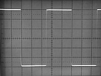
The .33 ohm resistors are inductive wirewounds, and the
inductor in the schematic represents that. When I laid the
board out, I anticipated a large capacitor in the decoupling,
but it didn't work out best that way, and I ended up trimming
the values against the following square wave at 10 KHz:
be asked here - "Why the .33 ohm resistors, inductor, and
10 uF cap?"
The .33 ohm resistors are inductive wirewounds, and the
inductor in the schematic represents that. When I laid the
board out, I anticipated a large capacitor in the decoupling,
but it didn't work out best that way, and I ended up trimming
the values against the following square wave at 10 KHz:
Attachments
I'm I right if I recognise a ZenV2 current source? I presume a variant with two IRFP240's would work as well?
/Hugo
/Hugo
Netlist said:I'm I right if I recognise a ZenV2 current source? I presume a variant with two IRFP240's would work as well?
I imagine so, although I did not try it. Note the 15,000 uF
cap in the current source charging circuit. An amplifier of this
low wattage will be paired with delicate drivers, and
avoiding turn-on thump is a priority.
😎
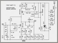
Nelson Pass said:Here we go
😎
Thanks Nelson Pass
Many girls and boys will be very happy
... like getting an early X-mas gift
I attach the image of your schematic
for those who want to take a quick look,
without download of original PDF
lineup
------------------------------------------------------------------------
this image, as all 'pass-materials', is now put with all the rest of my collection in folder C:/My Documents/Nelson Pass
I have separate folders, for like 60-70 other audio persons and diyaudio members, too.
Including one folder for 'lineup circuits and stuff', I have manage to find in this forum + world wide web
😉
Attachment:
First-watt-f2-sch.png
Attachments
Netlist said:..........................
Is there a particular reason to do the series/parallel resistor bank instead of one or two resistors?
/Hugo
certainly like always............Papa have it muuuuucho in stock........

not to mention few possible technicall reasons...
So, are you saying that a current source with P-channel devices is more immune to those thumps than an N-channel version? Or that a 15.000µF cap can not be used in a N-channel version? No, can’t be… although …is there a relation?
/Hugo
/Hugo
A different method for slow charge would be required to
bring up the N channel current source. No doubt it could
be done easily, and no doubt one of you will come up with
the appropriate variation. 😎
bring up the N channel current source. No doubt it could
be done easily, and no doubt one of you will come up with
the appropriate variation. 😎
Babowana said:What is the function of R1 (1M)?
Thanks, Nelson.
protection;
in case that preceding stage doesn't have same purpose resistor after coupling cap.
Papa must put this there,his amp is (sort of) commercial.
you are not obliged to do the same
- Home
- Amplifiers
- Pass Labs
- DIY F2 clone