I tried to take both measurements tonight. I am using the built in sound card on my computer and the generator in REW to create the signal. I am running an 8 ohm dummy load and measuring at the input to the amp.
To get an idea of the frequency response I varied the input frequency to the amp and measured the voltage of the output - I did not see any variation in the output voltage of the amp from 20 Hz to 20,000 Hz, but it did drop off a little at 10Hz. A pretty crude test, but the results seem ok.
I am having some trouble obtaining the FFT measurement, probably due to my inexperience. The questionable measurements I have now show that I need to have a 5 Vrms output on the amplifier to get a second harmonic peak make it above what I think is a -50dBV noise floor. I'll try again tomorrow.
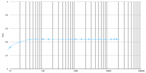
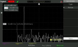
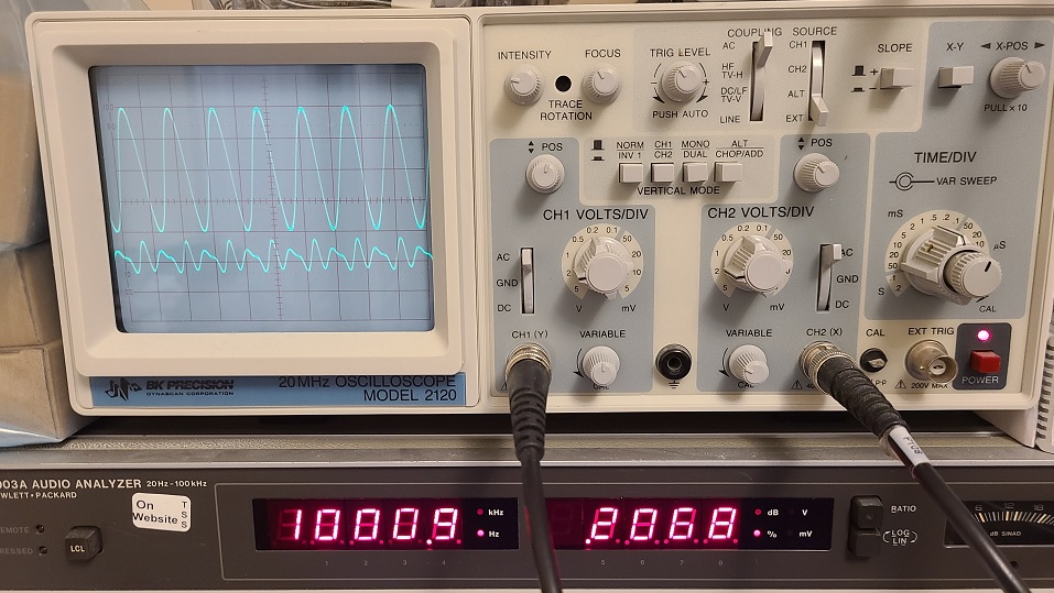
The images below show what i am measuring for frequency response and the best I can do for the FFT.
The frequency response starts to drop off below 20 Hz, but is flat from there up to 20,000 the highest frequency measured.
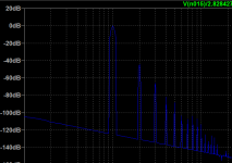
The FFT shows a ~47dB difference between the fundamental and the second harmonic. These measurements were taken at 1000Hz and 5.2 Vrms or about 3.4W output. If I am getting the math right, this is about .45% distortion. The First Watt distortion chart for the F2J shows about .6% THD at this power level. So allowing for an increase due to higher order distortion, I think my amp measuring .45% seems like it is in the ball park.
Any recommendations of what to try next? I was considering trying a different C3, maybe making a 12,000 uF bank of Nichicon KZ or Silmic II? Anyone know what type of capacitor was used in the real F2J?
Is it possible that this amp/speaker combo just is not a good pairing?
The frequency response starts to drop off below 20 Hz, but is flat from there up to 20,000 the highest frequency measured.
The FFT shows a ~47dB difference between the fundamental and the second harmonic. These measurements were taken at 1000Hz and 5.2 Vrms or about 3.4W output. If I am getting the math right, this is about .45% distortion. The First Watt distortion chart for the F2J shows about .6% THD at this power level. So allowing for an increase due to higher order distortion, I think my amp measuring .45% seems like it is in the ball park.
Any recommendations of what to try next? I was considering trying a different C3, maybe making a 12,000 uF bank of Nichicon KZ or Silmic II? Anyone know what type of capacitor was used in the real F2J?
Is it possible that this amp/speaker combo just is not a good pairing?
Attachments
Last edited:

any other amp as comparison , trying other source ?
I just biased up my BA-3 last week and it sounds great! Not as much bass with the Vulcans as the F2J, but much clearer. It also sounds great with some 4 ohm Vifa/Scanspeak 3 way towers I built years ago, the bass is so clear and precise that it makes me think I never had an amp that could handle the low impedance 10" woofers before.
Eventually I will build the DCG3 preamp that I have parts for, maybe that will help with the 10K input impedance of the F2J. Although I though the B1 would have helped with this too...
Do you think there would be any value in changing the output electrolytics, or is this just a waste of time and money?
Thanks for the input Zen Mod, as always you are very helpful.
changing caps can only bring it closer to your taste, but can't cure-it-all
find a reason why you're not satisfied - it's either source side or speaker side
for starters - try feeding it with anything which has headphones output with volume
I remember having some amps in Yore, and I was happiest (then) feeding them ditto from crappy Technics CD headphones out
that will tell some ......
Hello, I have read this thread very carefully, because I have built an open baffle speaker and have it converted to current drive. I don't want to go back!
So I think it would be a good idea to build a F2J, because I could do with a little more power than now.
The SemiSouth Sic Mosfet has long been discontinued, even the Company does not exist any more. So I have browsed the net to look for something similar, but I don't know if there is any useable candidate, but nevertheless I would like to show my results here, probably there are experts to help:
- I have not found a SiC jFet normally off,
so there is no direct replacement for the SemiSouth
- There is a jFet normally open from United Sic:
https://unitedsic.com/datasheets/DS_UJ3N065080K3S.pdf
So I thought it could be a solution
to add a small power supply to generate the negative grid voltage.
- There is another very special device from United Sic, the UF3C065080K3S
quote:"This SiC FET device is based on a unique ‘cascode’ circuit configuration,
in which a normally-on SiC JFET is co-packaged with a Si MOSFET to produce
a normally-off SiC FET device."
United Silicon Carbide Inc. UF3C065080K3S - United Silicon Carbide Inc.
All the Sic Fets I have looked at have beautiful output characteristics, there is no "knee", they look even better than the SemiSouth, but they are no jFets.
I have no idea, if my findings are meaningful at all, but I like to learn, and maybe there is a chance to build the F2 in the future. Thank you.
Question for Papa or any of the attending gurus:
Can I use 2SJ201/2SK1530 in F2 and what would need to be changed in the circuit? and maybe dissipate a bit less then 75W/channel? I have 4 pairs of these which I am looking to put to a good use and I wonder if that could be 4 channels of f2 (just for the sake of trying something different).
p.s. I am not into super sensitive full rangers but I am hoping that I could get away with just a few watts for the upper mid and treble in a multi amped setup; if that fails there's always the trusted ACAs for me to fall back onto 🙂
Is the change in R6 between F2 and F2J required because of the removal of Z1 and R2 (protection) or is it to handle the difference in Vgs of the SS part (1.2V) vs the IRF part (4.xV)?
If I wanted to try something with 2.8V Vgs do I have to use a different value for R6? Any circuit changes needed?
I tried this part with 8.2K in R6 and it's not amplifying. The board was verified working well before removing the IRFP240 and switching R6 from 100K to 8.2K.
Blocked
If I wanted to try something with 2.8V Vgs do I have to use a different value for R6? Any circuit changes needed?
I tried this part with 8.2K in R6 and it's not amplifying. The board was verified working well before removing the IRFP240 and switching R6 from 100K to 8.2K.
Blocked
look at graphs of said part datasheet
you need to obtain gate biasing voltage of at least {7V, plus voltage across source resistor group}, to open darn thing
use DVM, put probes on gnd and inner side of C1, and see where twiddling with P1 is getting you
edit: increase of C1 and R6 decrease, was Papa's adjusting for somewhat greater gate current of SJEP part, vs. our trusty IRFP; I believe you're good with same values, hard to believe that Cree's gate is even hungrier
Last edited:
Thank you Mighty Zen Mod! I think I may have been fooled by the lowered transconductance on this one but didn't think the difference would have been so dramatic (5.2 for Cree vs 6.9 for IRF). I saw traces on my scope but was expecting more than almost flat line but anyway, the important thing is I eventually installed pin headers in R6 so I could play with values and ended up putting in 20K. With 8.2K, I could only get 8.78V between C1 and GND.
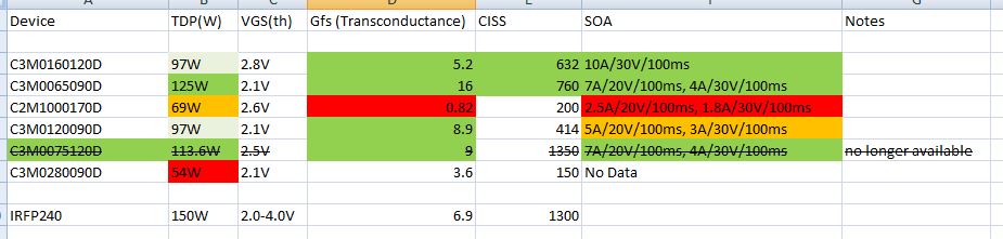
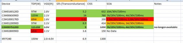
Long story short - it works and I have a Cree F2J with C3M0160120D alive for at least 3 hours of running and it hasn't melted into nuclear waste pile yet. Cree actually has SOA data for these but I did like a good greedy boy and read the NASA paper so understand that this means nothing for a device meant for to be used for switching ... but weren't the Tokin parts meant for switching too? 😉
Anyway, the experiment is a success if the intention was to build an F2 with much lower distortion. With IRF and about 16V (p-p), I was seeing about 5.8% distortion and now with the Cree (higher input voltage due to lower gain) but still at 16V (p-p), the distortion is down below 1% at 0.744%.
It sounds nice but it's still on parole - it's not allowed to play on the Frugalhorns until I have 2 channels built. For now I'll continue testing this to make sure it doesn't create a black hole.
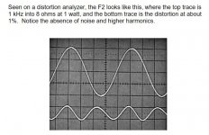
F2 (R6 100K - IRFP240) THD 5.8%

F2J (R6 20K - Cree C3M0160120D) THD 0.74%

In both pictures, the bottom trace is the residual. It looks like F2 was 2nd harmonic negative phase and F2CJ (Cree-J) has mix of 2nd and 3rd.
I already did F6 with different Cree and changed 2 blue leds for 4 greenies and it's still alive too but too bad that device is no longer available - C3M0075120D. The Ciss is nothing special on that one though. Different story for another thread.
Cheers,
Twitchie
Summary of Cree data for the devices I have:
Long story short - it works and I have a Cree F2J with C3M0160120D alive for at least 3 hours of running and it hasn't melted into nuclear waste pile yet. Cree actually has SOA data for these but I did like a good greedy boy and read the NASA paper so understand that this means nothing for a device meant for to be used for switching ... but weren't the Tokin parts meant for switching too? 😉
Anyway, the experiment is a success if the intention was to build an F2 with much lower distortion. With IRF and about 16V (p-p), I was seeing about 5.8% distortion and now with the Cree (higher input voltage due to lower gain) but still at 16V (p-p), the distortion is down below 1% at 0.744%.
It sounds nice but it's still on parole - it's not allowed to play on the Frugalhorns until I have 2 channels built. For now I'll continue testing this to make sure it doesn't create a black hole.
F2 (R6 100K - IRFP240) THD 5.8%
F2J (R6 20K - Cree C3M0160120D) THD 0.74%
In both pictures, the bottom trace is the residual. It looks like F2 was 2nd harmonic negative phase and F2CJ (Cree-J) has mix of 2nd and 3rd.
I already did F6 with different Cree and changed 2 blue leds for 4 greenies and it's still alive too but too bad that device is no longer available - C3M0075120D. The Ciss is nothing special on that one though. Different story for another thread.
Cheers,
Twitchie
Summary of Cree data for the devices I have:
Attachments
I believe you can up that R6 back to prescribed 47K
in case you need a smidge more positive voltage at gate ( too low Iq), increase R5 to 3K3, decrease R4 to 1K
tell us , with what gate voltage you did end, and what Iq you got
it could be handy for other Greedy Boyz, wanting to recreate your adventure 🙂
in case you need a smidge more positive voltage at gate ( too low Iq), increase R5 to 3K3, decrease R4 to 1K
tell us , with what gate voltage you did end, and what Iq you got
it could be handy for other Greedy Boyz, wanting to recreate your adventure 🙂
Had some time to set it back up to take more measurements. Have not changed any values but have not adjusted for symmetrical clipping yet. The low gain means I have to feed it with more than 4V on the input to drive it into clipping and I'm afraid to do that. On test speaker it plays plenty loud so I think I am going to keep it like this but Dennis is asking me problematic questions so I have to dismantle it a few more times 😉
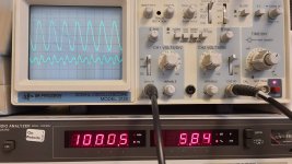
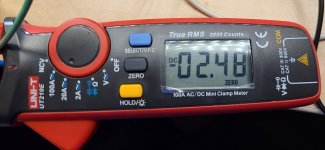
So gate voltage (still moving as it warms up - it drops so negative tempco?) was around 8.5V and Iq on ZM recommended clamp meter was 2.55A and stable as it warmed up.
So gate voltage (still moving as it warms up - it drops so negative tempco?) was around 8.5V and Iq on ZM recommended clamp meter was 2.55A and stable as it warmed up.
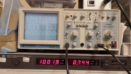
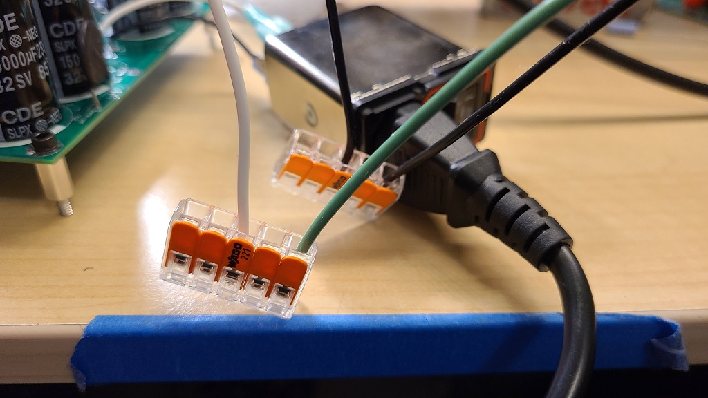
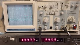
More pictures, less words
Life savers - must have for lazy greedy boyz
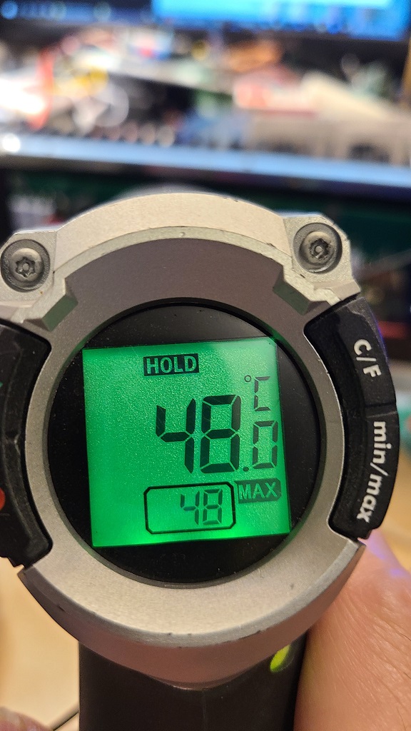
Stable heatsink temp - 48C - I think this is 'yikes'
Gate voltage at temp - 8.44V
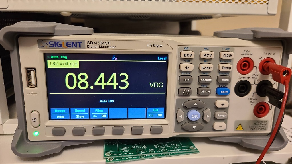
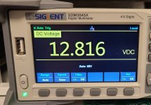
Drain voltage at temp - adjusted for minimum THD, not checked for symmetrical clipping but looks pretty close to 1/2 rail - 12.81V

What Papa said about F2 - about 1% @1W into 8 ohms
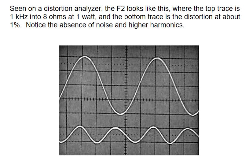
In F2J article, Papa says new device has about 1/3 of the THD of F2 and in this thread or somewhere, Papa says SS/F2J has about 1/5 of THD of F2. So the target is anywhere from 0.2-0.3% THD @1W into 8 ohms
We have a winner! - 1/5th THD or 0.2% @1W into 8ohm
For whatever reason, I don't get a trace when I connect + to OUT+ (GND) and - to OUT-(C3/output) so my connections are actually reversed ... this means positive phase 2nd(ish) becomes negative phase 2nd(ish). Papa is a genius! 😀
Still have 2 or 3 more devices to test. SS, the other Cree and a mystery part (for Dennis) ... maybe a Genesic too. Covid is boring, experimenting is fun
Cheers,
Twitchie
Life savers - must have for lazy greedy boyz
Stable heatsink temp - 48C - I think this is 'yikes'
Gate voltage at temp - 8.44V
Drain voltage at temp - adjusted for minimum THD, not checked for symmetrical clipping but looks pretty close to 1/2 rail - 12.81V
What Papa said about F2 - about 1% @1W into 8 ohms
In F2J article, Papa says new device has about 1/3 of the THD of F2 and in this thread or somewhere, Papa says SS/F2J has about 1/5 of THD of F2. So the target is anywhere from 0.2-0.3% THD @1W into 8 ohms
We have a winner! - 1/5th THD or 0.2% @1W into 8ohm
For whatever reason, I don't get a trace when I connect + to OUT+ (GND) and - to OUT-(C3/output) so my connections are actually reversed ... this means positive phase 2nd(ish) becomes negative phase 2nd(ish). Papa is a genius! 😀
Still have 2 or 3 more devices to test. SS, the other Cree and a mystery part (for Dennis) ... maybe a Genesic too. Covid is boring, experimenting is fun
Cheers,
Twitchie
Attachments


Can I use 2SJ201/2SK1530 in F2 and what would need to be changed in the circuit? and maybe dissipate a bit less then 75W/channel?
Hi Koja, did you have a chance to build F2 with 2sk1530? Have you measured the THD? I have 20-30 of these MOSFETs and I am thinking of building a second F2. The gain of the amp will be higher than with Semisouth or IRFP240.
- Home
- Amplifiers
- Pass Labs
- DIY F2 clone