Phew, quite a lot of posts since I last checked! I think this is the first time I've seen someone using Denis Sbragion's DRC filters on a DSP chip. This is very interesting.
I haven't had chance to post in a while as I've been slaving away for the past three days designing an FIR filter for FPGA's using Verilog. I don't have a huge amount of experience with Verilog programming, but I've got quite far (considering it was pretty much all from scratch).....
I now have a 16-tap FIR filter block, and you can easily cascade the block to add more taps. It's all done in parallel, so as soon as the first sample is received (24bit I2S format), all taps are calculated simultaneously (on the next system clock tick) and the result is sent to the output block. The output block then waits for the next I2S bitclock and starrts outputting the filtered result straight away. This means that there's only half a sample delay between the input and output (I'll probably change this to one sample delay.)
It's still at early stages atm, and it's only set up for 24bit filter coefficients, but the simulations suggest it should work. The coefficients could be quite easily loaded by a cheap PIC chip or something by "clocking in" the words. (or possibly via USB.)
I know there's a lot of talk about dedicated DSPs etc, but I think the low-level nature of FPGA design makes things much easier to understand (and easier to program.) This should make it more accessible, and easy to understand for anyone familiar with DACs and I2S protocols. It's also much easier to add more channels (if they will fit) and this can be done by a simple "drag and drop"! Of course, the other main aim is to make it economic too.
A few questions though.....
Roughly how much does the ADSP-21369 ez kit cost?
After 16 taps are multiplied and the totals added, I end up with a 52bit wide result. How is this supposed to be scaled down to fit the 24bit output?
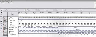
I've attached a screenshot of the simulation waveforms. "i2s_datain" is the serial data from the source, "result" is the filter result. The result will be the same as the input, as only one coefficient is loaded, and it's set to "1". Please note that an actual I2S sample would be more like 20us long rather than ~1500ns that it is in the simulation!
OzOnE.
I haven't had chance to post in a while as I've been slaving away for the past three days designing an FIR filter for FPGA's using Verilog. I don't have a huge amount of experience with Verilog programming, but I've got quite far (considering it was pretty much all from scratch).....
I now have a 16-tap FIR filter block, and you can easily cascade the block to add more taps. It's all done in parallel, so as soon as the first sample is received (24bit I2S format), all taps are calculated simultaneously (on the next system clock tick) and the result is sent to the output block. The output block then waits for the next I2S bitclock and starrts outputting the filtered result straight away. This means that there's only half a sample delay between the input and output (I'll probably change this to one sample delay.)
It's still at early stages atm, and it's only set up for 24bit filter coefficients, but the simulations suggest it should work. The coefficients could be quite easily loaded by a cheap PIC chip or something by "clocking in" the words. (or possibly via USB.)
I know there's a lot of talk about dedicated DSPs etc, but I think the low-level nature of FPGA design makes things much easier to understand (and easier to program.) This should make it more accessible, and easy to understand for anyone familiar with DACs and I2S protocols. It's also much easier to add more channels (if they will fit) and this can be done by a simple "drag and drop"! Of course, the other main aim is to make it economic too.
A few questions though.....
Roughly how much does the ADSP-21369 ez kit cost?
After 16 taps are multiplied and the totals added, I end up with a 52bit wide result. How is this supposed to be scaled down to fit the 24bit output?
I've attached a screenshot of the simulation waveforms. "i2s_datain" is the serial data from the source, "result" is the filter result. The result will be the same as the input, as only one coefficient is loaded, and it's set to "1". Please note that an actual I2S sample would be more like 20us long rather than ~1500ns that it is in the simulation!
OzOnE.
Attachments
OzOnE_2k3 said:Phew, quite a lot of posts since I last checked! I think this is the first time I've seen someone using Denis Sbragion's DRC filters on a DSP chip. This is very interesting.
I haven't had chance to post in a while as I've been slaving away for the past three days designing an FIR filter for FPGA's using Verilog. I don't have a huge amount of experience with Verilog programming, but I've got quite far (considering it was pretty much all from scratch).....
I now have a 16-tap FIR filter block, and you can easily cascade the block to add more taps. It's all done in parallel, so as soon as the first sample is received (24bit I2S format), all taps are calculated simultaneously (on the next system clock tick) and the result is sent to the output block. The output block then waits for the next I2S bitclock and starrts outputting the filtered result straight away. This means that there's only half a sample delay between the input and output (I'll probably change this to one sample delay.)
It's still at early stages atm, and it's only set up for 24bit filter coefficients, but the simulations suggest it should work. The coefficients could be quite easily loaded by a cheap PIC chip or something by "clocking in" the words. (or possibly via USB.)
I know there's a lot of talk about dedicated DSPs etc, but I think the low-level nature of FPGA design makes things much easier to understand (and easier to program.) This should make it more accessible, and easy to understand for anyone familiar with DACs and I2S protocols. It's also much easier to add more channels (if they will fit) and this can be done by a simple "drag and drop"! Of course, the other main aim is to make it economic too.
A few questions though.....
Roughly how much does the ADSP-21369 ez kit cost?
After 16 taps are multiplied and the totals added, I end up with a 52bit wide result. How is this supposed to be scaled down to fit the 24bit output?
I've attached a screenshot of the simulation waveforms. "i2s_datain" is the serial data from the source, "result" is the filter result. The result will be the same as the input, as only one coefficient is loaded, and it's set to "1". Please note that an actual I2S sample would be more like 20us long rather than ~1500ns that it is in the simulation!
OzOnE.
Welcome to the world of verilog!
I think that you will run out of multipliers pretty fast when you try to cascade blocks for longer FIR filters.
Since the data will be comming in at a pretty low rate, assuming 16 bits at 48kHz, we are talking 0.768Mhz!
With a simple RTL design you should be able to synthesize to at least 150-200MHz, thus a iterative approach can be implemented, in which for each incomming data sample the multiplier block is used say 200 times at 150MHz on the same sample but using different coeficients.
The final result needs to be scaled back to the 24 bits domain by dividing by a constant that will be related to the filter length.
OzOnE_2k3 said:
Roughly how much does the ADSP-21369 ez kit cost?
OzOnE.
You can order it directly from Analog. 495$
Big minus is that you get only 90 day trial licence for free for VisualDSP++, the only development tool. After that program memory is restricted to 25% and use of debugger is not allowed. It's pity, but its not slowing down my development. Someone said in this thread that the real license cost $3,500
Originally posted by cph2000
The final result needs to be scaled back to the 24 bits domain by dividing by a constant that will be related to the filter length.
Surely an arithmetic shift would do this better?
Originally posted by OzOnE_2k3
How is this supposed to be scaled down to fit the 24bit output?
To answer this original question more fully, the value really needs to be dithered for the best results. To achieve this you should add TPDF dither noise and then round the 52-bit value to 24 bits in length.
Some pseudo-C-code for an efficient 32-bit signed dither generator (it's an LCG based on the Super Duper values) could look like this:
Code:
int dither() {

static unsigned int rpdf1, rpdf2=1;
rpdf1 = (rpdf2 * 69069) % (2^32);
rpdf2 = (rpdf1 * 69069) % (2^32);
return ( (int) ((rpdf1>>1) + (rpdf2>>1)) );
}
Unless I've written it wrong, this function should return you a 32-bit signed TPDF random number. For use on 32-bit hardware like a PC, the modulo operations can be omitted - they will be done for free in the ALU. I imagine this function could be ported easily to VHDL/Verilog, but I don't know how to myself.
If you have a 52-bit result that you want to scale to 24-bits, then:
- Arithmetically shift the output of this function right by 4 places (so it is 28 bits long),
- Add it to the 52-bit result,
- Add 2^(-25) to the result to change the truncation that follows into a rounding operation (so there is no negative 0.5LSB DC offset), and
- Take the top 24 bits as your result.
Originally posted by DSP_Geek
32 bits gets you a dynamic range of 2*10^-9, so that leaves about 86 dB after ONE filter of room correction.
I don't quite know what you're saying there. Quantizing the coefficients moves the poles/zeros around a bit, so affects the frequency response of the filter. So we could design a room-correction filter with coefficients of a certain length and potentially have the filter "miss" the resonance it's trying to correct. But that's easy to check on a case-by-case basis. And I don't see what that has to do with the dynamic range of anything. But maybe I've just misinterpreted what you're saying.
If you're talking about noise-gain then I don't know the exact point at which it becomes a problem - but I do know that at 44.1kHz, a 32-bit double-precision-feedback biquad with an Fc of 1Hz and a Q of 30 displays no noise gain at all, even when looking at a full 32-bit output. So I can't imagine any possible filter specification, (even if it's running at a samplerate that's a few times higher), that's going to have a problem with noise gain at useful room correction frequencies (>10Hz?).

Originally posted by veskelin
Someone said in this thread that the real license cost $3,500
Damn straight. An even bigger minus is that to program/debug any hardware other than an EZ-kit (basically, anything anyone would actually want to use for a final incarnation this project!) requires the purchase of their hardware programmer. And those bad boys aren't cheap either. I think somewhere around $4000 for the high-speed one. There is a cheaper, slower one but I'm not sure about its cost.
Hi,
@veskelin: That's not too bad a price for the EZ kit I suppose, but I'm sure if I spent that much on a nice FPGA and a prototype PCB it could manage 6 channels of fitering with not too much effort.
@Winfeather: I think this is where the maths go over my head a bit. I have basic knowledge of binary maths but I nearly always have to look things up on the Web just to achieve what would be a simple task for others.
I can understand parts of this....
- Arithmetically shift the output of this function right by 4 places (so it is 28 bits long),
- Add it to the 52-bit result,
- Add 2^(-25) to the result to change the truncation that follows into a rounding operation (so there is no negative 0.5LSB DC offset), and
- Take the top 24 bits as your result.
...but when you say shift the output right, I'm not sure where you're getting the 24bit output from at first if the source is 52bits and the dest is 24bits?
I can shift bits around, create copies of the source and add, multiply, divide etc. But even then I'm still learning Verilog, so have to look up some of the commands / operators / examples. Also, I'm only working with integers (well, whatever raw data is input from the source) so I don't know if any of this data is floating point or whatever?
Is 2^(-25) literally 0.0000000298023223876953125 ? If so, I wouldn't have a clue how to add this to the data I'm working with.
Does 24bit I2S DAC data represent unsigned / fixed-point integers? What I can tell you is that if I divide the filter output by the number of filter taps, the software (Quartus II) rounds the result itself....
eg. at the moment, I have 48 taps. In the simulation I have a result of 11,897,039. If I divide this result by 48 I get 247,854 instead of 247,854.97916666. So, I can see where the dithering would need to come into it.
I was wondering if there was a set method used on the DSP chips after FIR filtering? (I know I can't just truncate the result into 24bits for obvious audible reasons.)
My usual way of working is to sort out the bigger problems with the design using simulation, then work out how big an FPGA I need, then order a pre-made dev board, then start playing with DACs and then I can sort out the smaller issues after things are up and running.
Again, please bear with me on this. I'm very determined and a quick learner, so I'm sure we can come up with something soon.
OzOnE.
P.S. I think it's an idea to start with 48KHz first, but do the 24bit filters matter too much for testing?
Originally posted by OzOnE_2k3
...but when you say shift the output right, I'm not sure where you're getting the 24bit output from at first if the source is 52bits and the dest is 24bits?
When I say to arithmetically shift right, I'm talking about the "two's complement" binary representation of the number you're using, so:
Original 16-bit number:
MSB 0100010100100000 LSB
Arithmetically shifted right by 4:
MSB 0000010001010010 LSB
Doing this simply introduces zeros into the most significant end of the number (if the MSB of the original number is zero, that is. It introduces ones if the MSB of the original number was one - this is important, because it maintains the sign of the original number). These duplicates of the MSB can be ignored and you've effectively reduced the length of the binary word.
Shifting right by one place performs the function of dividing the value of the number by 2 - this works for both positive (MSB=0) and negative (MSB=1) numbers in two's complement.
In terms of taking a 24-bit result out of a 52-bit value, all "right-shift by 28 places" means is to take the 24 most-significant (i.e. leftmost) bits of the 52-bit value as the result. All of this said, shifting numbers is likely more relevant to using a DSP than an FPGA, because with an FPGA you can probably just take a subset of bits from a word to use in a subsequent operation. It's all equivalent, it just depends how you think about it.
Originally posted by OzOnE_2k3
Is 2^(-25) literally 0.0000000298023223876953125 ? If so, I wouldn't have a clue how to add this to the data I'm working with.
Yes. But it's more commonly known as:
0.0000000000000000000000001
in binary 😀
This value is simply half of one LSB, since your data is 24 bits long, and is added to cancel out the -0.5LSB offset that is caused by a truncation. It's not essential to perform this step, and the dither will still work - but it's just "correct" to get rid of the offset.
Originally posted by OzOnE_2k3
eg. at the moment, I have 48 taps. In the simulation I have a result of 11,897,039. If I divide this result by 48...
This doesn't really need talking about now, but I thought I might as well mention it since I'm here: you don't need to divide by the number of taps. The result you come out with be the right size already. It will need chopping down because it's got too many bits of precision, yes. But the chopping happens from the bottom end of the word (precision is lost, but actual magnitude is not significantly altered) and the amount you remove just depends on how many bits you're able to use as your result. If you're able to use all 52 bits then you just use them as-is. No scaling or shifting or anything.
Originally posted by OzOnE_2k3
I was wondering if there was a set method used on the DSP chips after FIR filtering? (I know I can't just truncate the result into 24bits for obvious audible reasons.)
Well you can, and lots of people do. Especially with 24-bit audio, because it's usually acceptable not to worry about the small amounts of distortion. But you're right, you shouldn't do it this way for the best results.
Anyway, my point was there's no set method. There are lots of ways of reducing the length of binary words after DSP operations (not just FIR filtering, but anything involving multiplies). Simple truncation is a valid one. Slightly better is rounding (discussed above by adding the 0.5LSB offset). Arguably the best is TPDF dithering, because it gives zero distortion of the signal and a constant noise level. If you're reducing the word length a lot, and have spare bandwidth from using a high sample rate, then noise-shaping might give better results again, but noise-shaping is very case-specific, and TPDF-dither works well in every case.
Originally posted by OzOnE_2k3
Does 24bit I2S DAC data represent unsigned / fixed-point integers?
As far as I know, I2S represents 24-bit fixed-point numbers in two's complement format. Any DAC datasheet should tell you, though. I'm just too lazy to look right now
Originally posted by OzOnE_2k3
P.S. I think it's an idea to start with 48KHz first, but do the 24bit filters matter too much for testing?
I think it is important, simply because 24 bits is half as much again as 16 bits, and is going to have an enormous impact on the amount of resources you use for things. So I think you should certainly take this into account when deciding which device to opt for.
There is something made that might be perfect for this.
it is called a "creamware luna" or "scope home"
they are a 3 SHARC pci card with digital and analog i/o
the sound on these cards is extremely good. the SHARC is a great "sounding" DSP and there is some rock solid quuality.
i have 3 of its bigger brothers together in a PC for 34 SHARCs and i have in the past created synthesizers and effects for musicians.
i was out of that for a while, and the company got sold (its now called soniccore) anyways i am waiting for my SDK key to start this again. then i could create the device for the smaller card. which can be put in a different machine.
I was thinking of also having a active crossover option or a seperate device (you can just "virtually" wire them together). those 3 SHARCs could easilly handle that , probably even for surround.
anyways those cards sometimes show up on ebay for as low as $200 depending on what plugins were registered to that card.
(paid plugins with keys can not be run on any other card besides the one it was bought for unless you officially transfer the key at the company)
if i made that device, of course it would be free or only donationware.
SHarc dsp's are in the third generation since the creamware cards. Original 2106x aren't even SIMD. One of such first gen Sharc is bout 60 mflops? 21369 = 2000 ? 
Hi, Wingfeather,
Ok, so I've got a 52bit result from the FIR taps.....
1011000001000000100001111100001100100000001000000100
So I then shift right 4 bits (where the LSB bits wrap)....
0100101100000100000010000111110000110010000000100000
Then add these two 52bit numbers together and take the top 24 bits as the new result.
But, I'm not sure where the extra bit comes into it. Do you mean to add an extra 25th bit before the two 52bit numbers are added so that the final truncation is rounded up to the nearest LSB?
Also, you said that it would be OK to take the top 24 bits and ignore the LSBs without sounding too terrible? This would be fine for testing and doesn't have to be perfect right away.
As far as the coefficient width, I meant that most DRC filters are 32bit precision - I've only programmed 24bit filter / tap widths atm, are 32bit filters really necessary?
I've just changed the design to 512 taps - Where it used to take only take 1 minute to compile, it now takes 20 minutes! Talk about an exponential increase. This makes simulation and debugging very difficult, but I know it can work now. It's fairly easy to add new taps (just wire them up graphically and hit the compile button), so I can work with say 64 taps until all the bugs are worked out then do a final compile later.
I didn't realize the data was signed. I think I need to do some serious research on DACs etc. because it should have been obvious that the numbers would represent positive and negative swings of the output. You can see I haven't played with DACs before! 🙂
I'm still struggling with things like dBfs vs analog scales!
BTW, thanks for your help so far.
OzOnE.
flshzug said:SHarc dsp's are in the third generation since the creamware cards. Original 2106x aren't even SIMD. One of such first gen Sharc is bout 60 mflops? 21369 = 2000 ?
cool so all my 34 chips could be replaced by 1 but how would i heat my house then?
newer does not always mean better. besides this is an inexpensive way to go. a new board made with blackfin or something would not be avaliable for cheap on ebay 😀
with a bit of luck they will release a card with a couple of those new chips if they can be compatible with old code, it would be pretty amazing to run some of those fantastic analog mono synth emulations with full polyphony!
stupid creamware did not bribe the music magazines enough 🙁 i hope soniccore do better!
I hope noone buys those cards after reading this topic, that company went bankrupt several times. Anyway, the new wave is fpga addon card processing DSD audio hehehe. 
Originally posted by OzOnE_2k3
Ok, so I've got a 52bit result from the FIR taps.....
1011000001000000100001111100001100100000001000000100
So I then shift right 4 bits (where the LSB bits wrap)....
0100101100000100000010000111110000110010000000100000
Then add these two 52bit numbers together and take the top 24 bits as the new result.
Ah, no. I must not have explained myself clearly. Let's recap:
The most basic way of getting an output is to truncate. So you take the 52-bit output from the FIR taps:
1011000001000000100001111100001100100000001000000100
and take the 24 most-significant bits of it:
101100000100000010000111
Done!
This is a simple truncation. Numerically, the effect is of rounding the 52-bit value down. To round the 52-bit value to nearest, you first add half an LSB before you do the truncation, thus:
1011000001000000100001111100001100100000001000000100
+
0000000000000000000000001000000000000000000000000000
=
1011000001000000100010000100001100100000001000000100
and then truncate that:
101100000100000010001000
(Note that the addition of the half-LSB is done at the full 52-bit precision)
This is the rounded output, and is what I'd recommend you do for testing purposes. It's a nice starting point because dither can be added easily later on without really changing how things are done. Both methods produce the same performance in terms of distortion and noise power, but the rounded one has no DC offset whereas the truncated one does.
Another quick point is that you don't wrap when you do this kind of shift (arithmetic). Bits off the bottom end of the word just get lost. I think a shift where you wrap is called a barrel shift, and is more of a bit-manipulation trick than a numerical one.
Originally posted by OzOnE_2k3
As far as the coefficient width, I meant that most DRC filters are 32bit precision - I've only programmed 24bit filter / tap widths atm, are 32bit filters really necessary?
This is kind've what me and DSP_Geek have just been talking about. I think (and I think he agrees) that for the IIR filters you'll need for room correction, 32-bit coefficients really are essential due to the low-Fc and high-Q nature of room resonant modes. I don't know myself what the coefficient sensitivity is like for FIR filters, though. I don't imagine sensitivity increases for filters with points of interest in the LF region - you just add more taps when you want that.
Another point to consider is that if you want 24-bit transparency (i.e. no distortion, and no more noise than a single lot of 24-bit dither) at the output of this thing then you'll need to do the maths at some higher level of precision. That doesn't necessarily mean doing it at full 32-bit, but it might be nice and simplify overall system design if you have a 32-bit "audio bus" which remains the same size throughout the entire DSP system. That's what I'd probably try and get first because you should easily be able to get 24-bit transparency from it and more of the building blocks might be reuseable. If the FPGA doesn't have the resources to do things this way though, then you're going to have to start cutting corners and I guess the exact required levels of precision will have to be investigated more thoroughly.
Wingfeather said:I don't quite know what you're saying there. Quantizing the coefficients moves the poles/zeros around a bit, so affects the frequency response of the filter. So we could design a room-correction filter with coefficients of a certain length and potentially have the filter "miss" the resonance it's trying to correct. But that's easy to check on a case-by-case basis. And I don't see what that has to do with the dynamic range of anything. But maybe I've just misinterpreted what you're saying.
If you're talking about noise-gain then I don't know the exact point at which it becomes a problem - but I do know that at 44.1kHz, a 32-bit double-precision-feedback biquad with an Fc of 1Hz and a Q of 30 displays no noise gain at all, even when looking at a full 32-bit output. So I can't imagine any possible filter specification, (even if it's running at a samplerate that's a few times higher), that's going to have a problem with noise gain at useful room correction frequencies (>10Hz?).
I wanted to avoid the term in case you hadn't run across it, but I am indeed speaking of noise gain, which can be horrific with low F and high Q. As you've discovered, single precision isn't enough under those circumstances, but there are other ways...
Wingfeather said:
This is kind've what me and DSP_Geek have just been talking about. I think (and I think he agrees) that for the IIR filters you'll need for room correction, 32-bit coefficients really are essential due to the low-Fc and high-Q nature of room resonant modes. I don't know myself what the coefficient sensitivity is like for FIR filters, though. I don't imagine sensitivity increases for filters with points of interest in the LF region - you just add more taps when you want that.
Actually, truncating coefficients to 24 bits won't mess you up too badly. It's the noise gain which bites you hard. On the other hand, this also points the way to saving a few cycles: you can run what I call half-double precision, or multiplying double precision data by single precision coefficients, so you need only two multiplies instead of four to generate a result.
Coefficient sensitivity in FIRs isn't too bad, especially as DSPs accumulate the result in a single accumulator so there's no intermediate truncations to mess up partial results as in IIRs. At a guess, one probably wants the quantization error to be no larger than 10^-2 of the mean coefficient value.
OK, I see now that you're adding the 25th bit so that when the 52bits are truncated, it effectively negates a -0.5LSB offset in the result. The 25th bit won't actually be part of the truncation as such, but represents a weighting of half an LSB (for the top 24 bits).
I did try to work out how to perform this with Verilog, but I have it working as a combinational (one step) process atm.....
if (latchen) begin
storage[23:0] <= datain[56:33];
...where "latchen" is just a pulse which happens after the next audio sample has been received, all taps have been shifted and the new filter result is available. (The filter result is connected to "datain[56:0]")
(atm, you can see it just puts the top 24 bits of "datain" into the storage register. The rest of this module just shifts the final result out to the I2S DAC.)
I can do some basic maths on the storage register after the new data is latched, but I think it would take a couple of clock cycles to do slightly more advance maths before truncation. But, I could just set the 25th bit permantly high on the "datain" input? That's basically what we're trying to achieve anyway?
What I can say is that the Quartus software definitely rounds down - if you just do a simple divide like 52469 / 128, it becomes 409 instead of 409.9140625 (although this is when working with integers anyway.)
Does high Q mean things like high / narrow peaks etc? So you basically need a higher precision to represent these things more accurately with less distortion noise? I mean, it shouldn't be too difficult to change to 32bit coefficients, which would match up with the default produced by DRC. But, there may be a bigger problem......
I've only now realized that the data is actually signed, so I would need to change all the taps and calculations to work with signed data. This would probably add a fair few logic cells 😱
The default filters produced by DRC are in 32-bit IEEE Float (0,24) format - that probably poses an even bigger headache for my current filter design. Oh well, if it wouldn't sound too bad to just convert the 32bit filters to 24bit first that would be fine.
Oh, just a quick thought, what about converting to unsigned on the input, then converting the output to signed again? Is this a fairly painless conversion?
I really just need to get a bigger FPGA and hook a DAC to it. I could then test the input and output blocks first by connecting the internal parallel word paths together.
OzOnE.
Hi,
Just a quick heads up about a DSP solution (info from a post on the Acourate user group) which is just the sort of thing we are talking about....
http://www.signalwizardsystems.com/
v2.5 is only two channels, but it looks like there's a much better one on the way. The first version can only do 527 taps at 48KHz, which is about 11ms though.
Of course, this is pretty much like any DSP eval kit, but it's good to see more things like this.
OzOnE.
EDIT: Just a tad pricey then....
http://www.saelig.com/miva/merchant.mvc?Screen=PROD&Product_Code=EZSWII&Category_Code=
I'm definitely in the wrong business!
Originally posted by OzOnE_2k3
But, I could just set the 25th bit permantly high on the "datain" input? That's basically what we're trying to achieve anyway?
Nope. 'fraid not. The example we used above works well to show you why: if the 25th bit is already a one, then when you add the 2^-25 it won't end up being a one. You can see that in the example, the one that is added carries all the way over that little group of ones in the original number. You really do have to do the full addition.
Originally posted by OzOnE_2k3
Does high Q mean things like high / narrow peaks etc? So you basically need a higher precision to represent these things more accurately with less distortion noise?
Yes. But no. The number of bits you use in the coefficients has nothing to do with the quality of the processing as such, it only affects how close the frequency response is to where you want it. Since the coefficients are quantised, there is actually set of discrete frequencies at which you're able to put the cutoff of an IIR filter. If you want the cutoff to be some frequency in between these locations, all you can do is use more bits in the coefficients.
Distortion/noise is another issue entirely, and has to with the dit-depth of the data path that goes through the filter and the way the feedback path is processed. It does need to be looked at to get a good filter, but can be potentially left until you've got a basic platform working.
Originally posted by OzOnE_2k3
I've only now realized that the data is actually signed, so I would need to change all the taps and calculations to work with signed data. This would probably add a fair few logic cells
Ah, yeah. Can't be helped though. I'm almost absolutely certain that you can't get away with converting everything to unsigned at the input: Assuming the system can represent numbers between -1.0 and 1.0, just consider a very basic case, where you multiply -0.5 * -0.5. That should give you 0.25 as the result. Converting to unsigned (shifting all numbers into the range 0 to 2) converts the expression into 0.5 * 0.5, which would give you 0.25 (-0.75 after you convert back). Other examples seem to give simiular results - the logic in the calculations just breaks down.
Originally posted by OzOnE_2k3
The default filters produced by DRC are in 32-bit IEEE Float (0,24) format - that probably poses an even bigger headache for my current filter design.
Gawd, yeah. Designing floating-point multipliers probably isn't very much fun, although I've never done it. Unnecessary, anyway. You can convert these numbers into 24-bit or 32-bit fixed point at the beginning and then not worry about it after that. That conversion's not going to affect much of anything.
Originally posted by OzOnE_2k3
I really just need to get a bigger FPGA and hook a DAC to it.
I'd love to collaborate with you on the implementation of all this (although I don't know verilog or VHDL, so I wouldn't be much help!), but I don't even have the time to look into it right now. Hopefully I'll be able to do more in the coming months - those Digilent boards are superbly priced and those big Hirose connectors are ideal for adding I/O to.
I've been following this thread with great interest and can offer my help wrt VHDL/FPGA (Altera/Xilinx) or Tools (Quartus/ISE)development, if needed.
best regards
Simon
best regards
Simon
Hi Simon.
I've tried using logic elements as shift registers and doing all the calulations in parallel, but I realize now (as everyone said) that it takes up far too many resources (and far too long to compile).
So, I've started on a design which processes the taps using raw clock speed (in a kind of serial fashion). The problem I'm having at the moment is that I'm using the RAM-based shift register megafunction (24bit wide / 32 taps), but the data never seems to get latched or output?
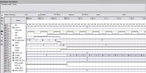
I've attached a simulation output which shows "shiften" going high. This is connected directly to the shift register's clken pin. The clk pin itself is connected to the master clock (100MHz atm for simulation).
The data input to the shift reg is directly from "i2s_data_word", so in theory it should at latch a few "11"'s into the shift reg when "shiften" is kept high for a few clocks?
Even if I keep shiften high for 36 clocks, the data from the input never appears at the output?
I'm guessing this might be a bit tricky to give suggestions on without the full diagram and code, but I'll send you the project if you'd like.
The basic layout is.....
First of all, the shift reg has a 2-way mux at it's input which allows either a new I2S word to be input, or it loops the shift register's output back to it's input. There is also a MAC block to process each tap and sum the results.
1. The coefficients are first loaded into a RAM block
2. MAC block is cleared / mux set to data input mode
3. Wait for the first input sample word to be arrive (from the I2S input block).
4. Shift the latest I2S word onto the shift reg (allowing the last word to "drop off the end")
5. Change the mux to "loop mode"...
6. Shift a tap (word) onto the loop
7. MAC (multiply / accumulate) the tap with the corresponding coef from the coef RAM block.
8. Repeat step 6 until all taps are processed.
9. Latch the final MAC result into the output block to output the new sample.
10. Restart (go to step 3)
All that really needs to happen with a convolution (as far as is my understanding), is that when a new sample arrives, the taps are shifted along and the previous last tap is discarded.
So, you just need to use a shift register to store the 2000 or so words on, then "MAC" all stored taps with their corresponding coefficients and output the final result before the next input sample arrives.
At 48KHz, a new sample arrives every 20.833us.
At 50MHz, to process 1024 taps (one tap per clock) would take 20.48us)
So, as long as the master clock is fast enough to process all stored taps before the next new sample arrives, it should work fine.
Or, you could partition the design so that you have two 512 tap shift registers,
two 512 word coef RAM blocks, and two multiplier blocks, then it would only take
512 clocks to process all the taps (results from both multiplier block are summed.)
But, after every 512 clocks, the position of the first stored tap would change
between "shift reg A" and "shift reg B", so you would have a fairly complex
setup to load the latest new sample etc.
The main aim atm is to use RAM blocks instead of logic cells so we can process some long filters without filling up the FPGA.
Hope all this makes sense. Trust me, I'm still trying to get my head around it!
OzOnE.
I've tried using logic elements as shift registers and doing all the calulations in parallel, but I realize now (as everyone said) that it takes up far too many resources (and far too long to compile).
So, I've started on a design which processes the taps using raw clock speed (in a kind of serial fashion). The problem I'm having at the moment is that I'm using the RAM-based shift register megafunction (24bit wide / 32 taps), but the data never seems to get latched or output?
I've attached a simulation output which shows "shiften" going high. This is connected directly to the shift register's clken pin. The clk pin itself is connected to the master clock (100MHz atm for simulation).
The data input to the shift reg is directly from "i2s_data_word", so in theory it should at latch a few "11"'s into the shift reg when "shiften" is kept high for a few clocks?
Even if I keep shiften high for 36 clocks, the data from the input never appears at the output?
I'm guessing this might be a bit tricky to give suggestions on without the full diagram and code, but I'll send you the project if you'd like.
The basic layout is.....
First of all, the shift reg has a 2-way mux at it's input which allows either a new I2S word to be input, or it loops the shift register's output back to it's input. There is also a MAC block to process each tap and sum the results.
1. The coefficients are first loaded into a RAM block
2. MAC block is cleared / mux set to data input mode
3. Wait for the first input sample word to be arrive (from the I2S input block).
4. Shift the latest I2S word onto the shift reg (allowing the last word to "drop off the end")
5. Change the mux to "loop mode"...
6. Shift a tap (word) onto the loop
7. MAC (multiply / accumulate) the tap with the corresponding coef from the coef RAM block.
8. Repeat step 6 until all taps are processed.
9. Latch the final MAC result into the output block to output the new sample.
10. Restart (go to step 3)
All that really needs to happen with a convolution (as far as is my understanding), is that when a new sample arrives, the taps are shifted along and the previous last tap is discarded.
So, you just need to use a shift register to store the 2000 or so words on, then "MAC" all stored taps with their corresponding coefficients and output the final result before the next input sample arrives.
At 48KHz, a new sample arrives every 20.833us.
At 50MHz, to process 1024 taps (one tap per clock) would take 20.48us)
So, as long as the master clock is fast enough to process all stored taps before the next new sample arrives, it should work fine.
Or, you could partition the design so that you have two 512 tap shift registers,
two 512 word coef RAM blocks, and two multiplier blocks, then it would only take
512 clocks to process all the taps (results from both multiplier block are summed.)
But, after every 512 clocks, the position of the first stored tap would change
between "shift reg A" and "shift reg B", so you would have a fairly complex
setup to load the latest new sample etc.
The main aim atm is to use RAM blocks instead of logic cells so we can process some long filters without filling up the FPGA.
Hope all this makes sense. Trust me, I'm still trying to get my head around it!
OzOnE.
Attachments
Hi,
Quick update, I've found that the shift register is actually "taps" X "distance between taps", so it does work, but not as I need it to.
ie. If I have a shift reg of 4 taps, with a "distance between taps" of 3, you have to shift 12 times to get an output. Oh well, I'll figure it out. I just need to get this part working in RAM 'cos it looks like the rest is almost working.
OzOnE.
P.S. A very Happy Christmas / Holiday / Hanukkah / etc. to you all!
Hi all,
Made a fair bit of progress with the FIR design.... I now have a 64 tap filter, which can easily be extended to 1024 of more taps and multiple channels. The main requirement is that the FPGA has enough RAM bits as the design takes very little logic resources.
A 1024 tap / 24bit coef filter will only take around 450 logic elements on a Cyclone II. The memory bits needed is roughly "taps X width", so a 1024 tap filter should only take around 25,000 bits.
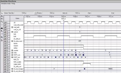
I've attached a screenshot of the filter after three audio samples have been processed. The screenshot shows that it is now working properly with signed data. The example shows a MAC between SHIFT_out and COEF_out, so it's basically doing.....
(11 * 62) + (2126 * 63) + (-437 * 64) = 106652
The result of the MAC is latched to the "storage" register in the I2S output block and the result sample is then output when LRCLK next goes low. So, as long as the master clock of the FPGA is fast enough to process all the taps, there is only one sample delay between a new sample arriving and the result of all taps being output.
Again, probably a fair amount of work to do and a few bugs here and there, but looking go so far.
OzOnE.
Made a fair bit of progress with the FIR design.... I now have a 64 tap filter, which can easily be extended to 1024 of more taps and multiple channels. The main requirement is that the FPGA has enough RAM bits as the design takes very little logic resources.
A 1024 tap / 24bit coef filter will only take around 450 logic elements on a Cyclone II. The memory bits needed is roughly "taps X width", so a 1024 tap filter should only take around 25,000 bits.
I've attached a screenshot of the filter after three audio samples have been processed. The screenshot shows that it is now working properly with signed data. The example shows a MAC between SHIFT_out and COEF_out, so it's basically doing.....
(11 * 62) + (2126 * 63) + (-437 * 64) = 106652
The result of the MAC is latched to the "storage" register in the I2S output block and the result sample is then output when LRCLK next goes low. So, as long as the master clock of the FPGA is fast enough to process all the taps, there is only one sample delay between a new sample arriving and the result of all taps being output.
Again, probably a fair amount of work to do and a few bugs here and there, but looking go so far.
OzOnE.
Attachments
- Status
- Not open for further replies.
- Home
- Source & Line
- Digital Source
- DIY DSP for Digital Room Correction