locky_z,
How do I load data without first having to run a measurement😕
The load data button only becomes active after doing a measurement. It is pretty annoying that I: 1) have to physically connect the tracer, 2) run the "get parameters" routine, 3) do a measurement, 4) delete the measurement, and only then can I 5) load a previous dataset........
The data file management is also not very transparent. It seems that all basic commands like "New", "Open", "Close" and "Save" have been replaced by only two that function as "Merge" and "Save as"😕
Cheers,
Nic
P.S. Thanks for the software update. It seems to have solved my data export problems.
No need online ,The data can be loaded.
Direct select 'Curve Control' page, and press 'Load data'.
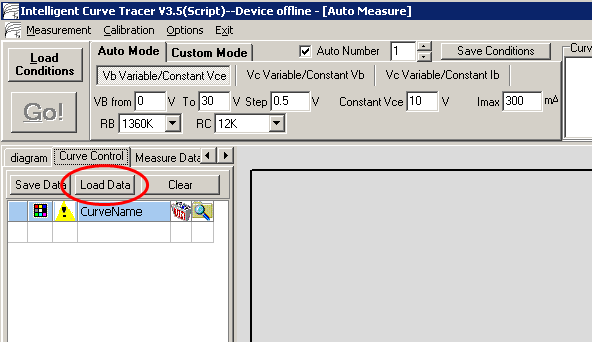
The 'save data' only save the row that checkbox is 'checked',
The targte file will be clear first then write.
So if you want append data,you need load file first and save again.
Direct select 'Curve Control' page, and press 'Load data'.
The 'save data' only save the row that checkbox is 'checked',
The targte file will be clear first then write.
So if you want append data,you need load file first and save again.
Attachments
I more than happy to help with tidy up of this but not good enough to start from scratch.
Your English is not to bad and if you get started we can get there...
I translated the document into english, not perfect though. 🙂
Attachments
I translated the document into english, not perfect though. 🙂
Thank you,
I translated the document into english, not perfect though. 🙂
Good going Peter . I had asked my wife (who is also from S'pore) to translate it but she said it was too technical.
software update(2012.8.12)
And script Introduction doc (chinese)
Thanks for the new release 🙂. Is there are changelog available to see what has been done in the new versions? Regards, Chris
Locky_z and others,
I do not intend to hijack this thread, it’s just that I would like to ask some information from those who have an original SMPS from HP. Also, the following information might be of use for anybody else building this tracer and purchasing a low-cost HP clone power supply.
I bought a low-cost new power supply from eBay Germany (~18 Euro), sold as a ‘replacement’ for the original HP. Of course, it had to be opened up, because:
The capacitor brand isn’t the best either, and because I’m ordering parts from Digikey anyway this week, I’ll order some good quality caps with it.
In other words, it gives a (subjective) feeling of some cost cutting.
Question #1: do such caps always have to be of different value (for some reason as circuit resonance/oscillation)?
Question #2: what are the capacitor values in the original HP power supply packs?
Question#3: I could fit in 2x 680uF caps (2310 mA RC each), would there be any reason not to do so?
Then, some more bad feelings. A jumper is installed where a resistor (jumper across R59 under the black cap in the picture below) is printed on the PCB: this jumper is between the output capacitors and the choke (the final outgoing cables are connected to the other side of the choke). Checking out the web learns that there is indeed very often a resistor to further reduce any remaining ripple.
Question #4: is there a resistor installed in the original HP power supply packs, and what is it value? What would be the power rating?
Finally, the board is missing loads of components according the silk printing. One missing component is a small ceramic filter cap (SMD cap on the solder side) bypassing the two electrolytic capacitors above, before the choke.
Question #5: is there a bypass cap (SMD on the solder side) in the original HP power supply pack? Should I add one? Note: there is a ceramic SMD bypass cap between the pins of the departing cable.
Many thanks in advance to anybody who would have some answers.
Footnote: the zero volt output is connected to the earth pin of the IEC connector via the second thin PCB, and locky_z’s design isn’t having (or not so many) HF bypass caps either. Hence, any suggestion for improvements here? How ‘low-noise’ or ‘low-ripple’ has the PSU to be anyway?
cheers


I do not intend to hijack this thread, it’s just that I would like to ask some information from those who have an original SMPS from HP. Also, the following information might be of use for anybody else building this tracer and purchasing a low-cost HP clone power supply.
I bought a low-cost new power supply from eBay Germany (~18 Euro), sold as a ‘replacement’ for the original HP. Of course, it had to be opened up, because:
- That’s what I do with any electronic device since childhood… 😀
- I want to remove the primary IEC connector and install a loose chassis-mounted one with a power switch in the middle.
- The outgoing secondary cable is in the way for putting this PSU inside an enclosure with the tracer PCB (like locky_z did himself in one of his pics).
The capacitor brand isn’t the best either, and because I’m ordering parts from Digikey anyway this week, I’ll order some good quality caps with it.
- The HV caps (Ltec, TY series) will be replaced by Nippon Chemi-Con KXG series
- The LV output caps (black = Lelon LXK, blue is Ltec LZG) will be replaced by United Chem-Com KY series
Of course I could just order exact replacements, but I have some hesitation; it looks like the lowest possible cost solution has been installed here… so if ordering anyway…. let’s get the right caps.
- The smaller black one is a Lelon LXK 330uF/50V, ESR = 0.059 Ohm @ 100 kHz, 1260 mA R.C.
- The larger blue one is a Ltec LZG, 560uF/50V, ESR = 0.034 Ohm @ 100kHz, 1960 mA R.C
In other words, it gives a (subjective) feeling of some cost cutting.
Question #1: do such caps always have to be of different value (for some reason as circuit resonance/oscillation)?
Question #2: what are the capacitor values in the original HP power supply packs?
Question#3: I could fit in 2x 680uF caps (2310 mA RC each), would there be any reason not to do so?
Then, some more bad feelings. A jumper is installed where a resistor (jumper across R59 under the black cap in the picture below) is printed on the PCB: this jumper is between the output capacitors and the choke (the final outgoing cables are connected to the other side of the choke). Checking out the web learns that there is indeed very often a resistor to further reduce any remaining ripple.
Question #4: is there a resistor installed in the original HP power supply packs, and what is it value? What would be the power rating?
Finally, the board is missing loads of components according the silk printing. One missing component is a small ceramic filter cap (SMD cap on the solder side) bypassing the two electrolytic capacitors above, before the choke.
Question #5: is there a bypass cap (SMD on the solder side) in the original HP power supply pack? Should I add one? Note: there is a ceramic SMD bypass cap between the pins of the departing cable.
Many thanks in advance to anybody who would have some answers.
Footnote: the zero volt output is connected to the earth pin of the IEC connector via the second thin PCB, and locky_z’s design isn’t having (or not so many) HF bypass caps either. Hence, any suggestion for improvements here? How ‘low-noise’ or ‘low-ripple’ has the PSU to be anyway?
cheers
I think I got myself the same SMPS (NETZTEIL FÜR HP 0957-2247 32V - 2500mA) and it works quite well "out of the box".
I had absolutely no problems with it and it is really just fine if you can live with its voltage and current limitations. I would not worry about tweaking anything in it as you are likely to do more harm than good. Why polish a turd?
Spend your money on DUTs🙂
I had absolutely no problems with it and it is really just fine if you can live with its voltage and current limitations. I would not worry about tweaking anything in it as you are likely to do more harm than good. Why polish a turd?
Spend your money on DUTs🙂
Device not found
Hello curve tracer user,
I connected the curve tracer in accordance to the manual.
The Power supply is the recommended HP 32V DC 2500 mA.
When I connected the USB cable the PC shows me "new hardware found and ready to use".
I started the software and followed the steps written in the manual.
But then the system shows me "device not found".
The com port is the right one.
I noticed that the heatsink is getting hot very quick and I made some measurement of the temperature (see picture attached).
In my opinion it's very hot.
Thank you in advance for your help.
Andreas
Attachments
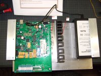
Did you insulate the screws going through the power transistors??
I don`t see the plastic bushings there..
I don`t see the plastic bushings there..
Screws are making contact with front face of transistors and you have multiple shorts. Always test transistors for sink isolation with DMM resistance check. Simple, fast and safe
I used plastic bushings and insulating foil.
Maybe one foil is damaged.
I will check it with a DMM tonight.
Thank you.
Andreas
Maybe one foil is damaged.
I will check it with a DMM tonight.
Thank you.
Andreas
the LM317 hot,may be 24V output wrong.
You can short socket 'X Y Z' and power on, if 24V 12V 5V and MCU is ok,you may hear some relay sound.
You can short socket 'X Y Z' and power on, if 24V 12V 5V and MCU is ok,you may hear some relay sound.
Last edited:
I did the DMM resistance check and it seems like that 3 transistors ( the red circles) have contact to the Aluminum-angle.
I removed the angle and find out that they have contact to the Aluminum ground-plate as well 😕
Then I removed the board from the ground-plate and everything works.
I did the DMM resistance check between the "red" transistors and the metal-ring fixture hole (yellow) and find out that they are connected.
I will fix the board with plastic bushings or plastic stands and then I hope it will work.
Does all the other user have plastic cases or fixed the board with insulation parts or is there something else I have to check?
Attachments
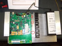
Hi Andreas,Does all the other user have plastic cases or fixed the board with insulation parts or is there something else I have to check?
could there be something wrong with your fixing to the ground plate? As I understood from your description, the function came back when the board wasn't fixed on the ground plate any more...
BTW, it's O.K. that the three parts on the side have connection to ground (the first is the 12V voltage regulator with Pin 2 to GND and the other two ones (Q1, Q4) are the PNP transistors with Collector connected to GND).
Mine is buildt into a steel case (only isolated the parts on the side) and everything works fine!
Regards,
Chris
You also no use heatsink and power on 32V, but the LM317 may have a little hot,
And you can measure LM317 output is 24V,
measure 7812 output is 12V,
78L05 output is 5V,
If the voltage not ok, may have some compent error.
And you can measure LM317 output is 24V,
measure 7812 output is 12V,
78L05 output is 5V,
If the voltage not ok, may have some compent error.
- Status
- Not open for further replies.
- Home
- Amplifiers
- Solid State
- DIY Curve Tracer for PC