Yes, I always use a LP filter on all preand power amp inputs.
But if you have one you can drop it.
Sometimes a base stopper is helpful to prevent oscillation. You might use around 47R carbon for this role however.
HD
But if you have one you can drop it.
Sometimes a base stopper is helpful to prevent oscillation. You might use around 47R carbon for this role however.
HD
I always thought this base stopper resistor was to prevent the base of the transistor from being 'overloaded' or something like that, did not occur to me this was to prevent oscillation. Or perhaps overloading and oscillation are related, don't know.Yes, I always use a LP filter on all preand power amp inputs.
But if you have one you can drop it.
Sometimes a base stopper is helpful to prevent oscillation. You might use around 47R carbon for this role however.
HD
Anyhow, it is probably wise to leave the filter where it is. Thank you AKSA!
You will see this filter on many amplifiers and its purpose is simply to prevent RF to be attenuated at the input. Nothing special, only preventative measure. In the past in Europe, people always complained that AM radio bled into their sound systems and I guess it has a historical reason.
Last edited:

Long & interesting thread, I want to make the Headphone amp for HifiMan Edition XS 18R 92dBs, could someone link me to the schematic if exist or the mod to use it?
TIA
TIA
This is the one you may want to take a look at: 24V versionLong & interesting thread, I want to make the Headphone amp for HifiMan Edition XS 18R 92dBs, could someone link me to the schematic if exist or the mod to use it?
Also, see
https://www.diyaudio.com/community/threads/diy-class-a-headphone-amp-suggestion.415623/post-7754585 and
https://www.diyaudio.com/community/threads/diy-class-a-headphone-amp-suggestion.415623/post-7754723
for lower power variations.
Last edited:
Yes, without R13 and C8, not needed.Is the attached schematic?
It can be operated at 24V supply voltage, but at 19V, Q2, R5, R6 dissipate less heat: 1.3W, 1.3W and 640mW respectively.
At 24V Q2, R5 and R6 dissipate 2W, 2.4W and 1.1W respectively.
Also you'll probably find a 19V power supply from an old broken laptop more easily than a 24V one.
Last edited:
True, but it also indicates that it can work with 16 ohm headphones (Merlin wants to use HifiMan Edition XS 18R headphones).And also R9, which is a fictive load for simulation purpose
What's the pourpose of L1, R11, C5 & C6. Filter the brick SMPS PSU?
What's the total power consumption?
What's the total power consumption?
Polyswitch R11 acts as a fuse, L1 and C6 are for filtering noise (from the SMPS), C5 for stabilizing supply voltage.What's the pourpose of L1, R11, C5 & C6. Filter the brick SMPS PSU?
Using a supply voltage of 19V: 3.4WWhat's the total power consumption?
Using a supply voltage of 24V: 5.7W
I am pretty sure you can but others in this thread may have suggestions on this. The original mentions a MJE350.Could I use other transistor for Q2 TIP42C
Last edited:
Yes. Master device (smaller) should be fast (100MHz or more)
and slave device should be slower (less than 70MHz.
This generally minimises oscillation.
HD
and slave device should be slower (less than 70MHz.
This generally minimises oscillation.
HD
Ok, cleared now, 3000uF per channel. It has a terrific dynamic range, the little heater 😁Thanks Nico very good advice.
M, your HPA draws almost 300ma from each channel and typically you would use at least 10uF per ma in the supply.
But test if the supply can cope with 3300uF per channel as many switch mode supplies complain.
Hugh
Finally after finishing this amp, the whole story, beware 🙂
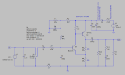
Studying and simulating this schematic it occurred to me that this design of AKSA and Nico Ras is --deceptively-- simple. Although it consists of only two BJT transistors and some other components, the value and probably also the quality of all components determine the outcome. So that is the case with the U2/R12 combination, the choice of transistors, the use of R13/C1 and R7, R5/R6, filtering the supply voltage and probably much more that I am not aware of.

I made the harmonics profile changeable by using a multi-turn pot (U2). The combination U2/R12 set to 27k results in nice harmonics and sound using my 80ohm headphones at 12V supply voltage. If you use headphones with a different impendance you may want to change the value of U2 to your liking. Or, if you want the least distortion possible you can set that as well. Increasing the supply voltage also changes the harmonics profile. So there are a few different, simple ways to modify the workings of the circuit, making this a flexible design.


Originally I removed R13 and C1 to save some space on the small 4x6cm prototyping board. I should not have done that. Testing it I noticed signs of oscillation so I had to add R13 and C1 again, and I also added R7 just to be sure. That helped to get rid of any possible oscillation.
The two TIP42C transistors are mounted onto the bottom of the case, sufficiently cooling them. It becomes barely warm over time.
I mounted the R5 and R6 5W resistors vertically to create some space on the board.
L1 and L2 are in fact one ferrite ring, + and - both wind around that ring, 14 turns of any isolated wire that you can find. Internal wires from UTP network cabling work well.
Be sure to connect the signal ground of all 'sound-carrying' components (volume pot, RCA connectors, output connector) to the correct, "clean" side of the ferrite ring, that is the left side of the inductor as seen on the schematic. If you do not you shall likely end up with a motorboating amp. The connection of GND to the aluminium case is switchable.
You may ask yourself what C7 is for. The 1nF capacitor prevents crackling sounds if turning the volume pot. I have the impression not everyone has that problem but I have, so I added it.
Just like the Formula3HP amp of Lineup that I made before I used a cast-aluminium case again to build it like a tank. One may call it industrial design but let's be honest, it is the best I can do to give it a somewhat nice robust finish without having too many tools to accomplish that.
After sanding and brushing the aluminium using WD-40 as a lubricant I coated it with, you guessed it, WD-40.
The color of the aluminium may become a bit darker over time, which I like because it gives some character to the design. After some time you can apply WD-40 again but I noticed that is not needed if the amplifier is not handled too much.
The enclosure is a Velleman G120B: 'sealed die-cast enclosure - aluminium - 171 x 121 x 55 mm', see https://www.velleman.eu/products/view?id=7327&lang=en. It is not the easiest case to use because the inside is not regular with all the protrusions and it is small. It was a bit of a puzzle to fit everything in but I somehow managed to do that.


In the bottom of the enclosure I made a 1cm hole beneath every board. Four 0.5cm holes at the top of the case then hopefully create a 'chimney effect' to cool the inside adequately. The holes in the prototyping boards that are left unsoldered help to distribute the warmth.
All this may not be necessary using 12V supply voltage but at 19V to 24V I expect it shall.

The boards are not fixed but fastened enough not to become loose. Especially the amplifier board is able to move vertically ever so slightly as the temperature of the transistors change. Silicone tubing is used as board standoffs.


Now the purpose of it all, the sound. First, there is hardly a thump switching it on or off. Then, the first words that come in mind are 'accurate', 'detailed', 'natural', and I should add the word 'very' to that, despite knowing the harmonics profile. Now I know what Michelag means when he calls it the 'Wire'.
I can clearly hear the acoustics and sometimes the sound extends beyond the headphones. If I get a shiver down the spine with a smile on my face there's nothing more to be desired...
Enough written and enough read. All in all it took some thought, effort and time to finish building my version of this amp but it is more than worth it! I am certain this amp deserves its own official name and its own thread.
Thanks again AKSA and Nico Ras!
Studying and simulating this schematic it occurred to me that this design of AKSA and Nico Ras is --deceptively-- simple. Although it consists of only two BJT transistors and some other components, the value and probably also the quality of all components determine the outcome. So that is the case with the U2/R12 combination, the choice of transistors, the use of R13/C1 and R7, R5/R6, filtering the supply voltage and probably much more that I am not aware of.
I made the harmonics profile changeable by using a multi-turn pot (U2). The combination U2/R12 set to 27k results in nice harmonics and sound using my 80ohm headphones at 12V supply voltage. If you use headphones with a different impendance you may want to change the value of U2 to your liking. Or, if you want the least distortion possible you can set that as well. Increasing the supply voltage also changes the harmonics profile. So there are a few different, simple ways to modify the workings of the circuit, making this a flexible design.
Originally I removed R13 and C1 to save some space on the small 4x6cm prototyping board. I should not have done that. Testing it I noticed signs of oscillation so I had to add R13 and C1 again, and I also added R7 just to be sure. That helped to get rid of any possible oscillation.
The two TIP42C transistors are mounted onto the bottom of the case, sufficiently cooling them. It becomes barely warm over time.
I mounted the R5 and R6 5W resistors vertically to create some space on the board.
L1 and L2 are in fact one ferrite ring, + and - both wind around that ring, 14 turns of any isolated wire that you can find. Internal wires from UTP network cabling work well.
Be sure to connect the signal ground of all 'sound-carrying' components (volume pot, RCA connectors, output connector) to the correct, "clean" side of the ferrite ring, that is the left side of the inductor as seen on the schematic. If you do not you shall likely end up with a motorboating amp. The connection of GND to the aluminium case is switchable.
You may ask yourself what C7 is for. The 1nF capacitor prevents crackling sounds if turning the volume pot. I have the impression not everyone has that problem but I have, so I added it.
Just like the Formula3HP amp of Lineup that I made before I used a cast-aluminium case again to build it like a tank. One may call it industrial design but let's be honest, it is the best I can do to give it a somewhat nice robust finish without having too many tools to accomplish that.
After sanding and brushing the aluminium using WD-40 as a lubricant I coated it with, you guessed it, WD-40.
The color of the aluminium may become a bit darker over time, which I like because it gives some character to the design. After some time you can apply WD-40 again but I noticed that is not needed if the amplifier is not handled too much.
The enclosure is a Velleman G120B: 'sealed die-cast enclosure - aluminium - 171 x 121 x 55 mm', see https://www.velleman.eu/products/view?id=7327&lang=en. It is not the easiest case to use because the inside is not regular with all the protrusions and it is small. It was a bit of a puzzle to fit everything in but I somehow managed to do that.
In the bottom of the enclosure I made a 1cm hole beneath every board. Four 0.5cm holes at the top of the case then hopefully create a 'chimney effect' to cool the inside adequately. The holes in the prototyping boards that are left unsoldered help to distribute the warmth.
All this may not be necessary using 12V supply voltage but at 19V to 24V I expect it shall.
The boards are not fixed but fastened enough not to become loose. Especially the amplifier board is able to move vertically ever so slightly as the temperature of the transistors change. Silicone tubing is used as board standoffs.
Now the purpose of it all, the sound. First, there is hardly a thump switching it on or off. Then, the first words that come in mind are 'accurate', 'detailed', 'natural', and I should add the word 'very' to that, despite knowing the harmonics profile. Now I know what Michelag means when he calls it the 'Wire'.
I can clearly hear the acoustics and sometimes the sound extends beyond the headphones. If I get a shiver down the spine with a smile on my face there's nothing more to be desired...
Enough written and enough read. All in all it took some thought, effort and time to finish building my version of this amp but it is more than worth it! I am certain this amp deserves its own official name and its own thread.
Thanks again AKSA and Nico Ras!
Last edited:
- Home
- Amplifiers
- Headphone Systems
- DIY Class A Headphone Amp suggestion