Wow.......really...really nice work.......Hey that Waybackmachine could I use it to go back when gas wasWaybackmachine managed to capture wongkm33's webpage one time, and with that, well worth details of the main and power PCB. Enjoy
1.87....and go back more to when Dynaco 416 power amps were 249.00......I have a few other items I
would need to pick up also.
Glad you liked the info ... and... 😆
I'm gonna compare the CAT to VSE RTP3D which is diff in and bal out. If I end up building a tube pre, I want it to be balanced such that I can properly utilize PASS XA circuitry. Also only fair to compared apples to apples since I am working on an XP/XS preamplifier. I really like balanced operation, through and through.
I'm gonna compare the CAT to VSE RTP3D which is diff in and bal out. If I end up building a tube pre, I want it to be balanced such that I can properly utilize PASS XA circuitry. Also only fair to compared apples to apples since I am working on an XP/XS preamplifier. I really like balanced operation, through and through.
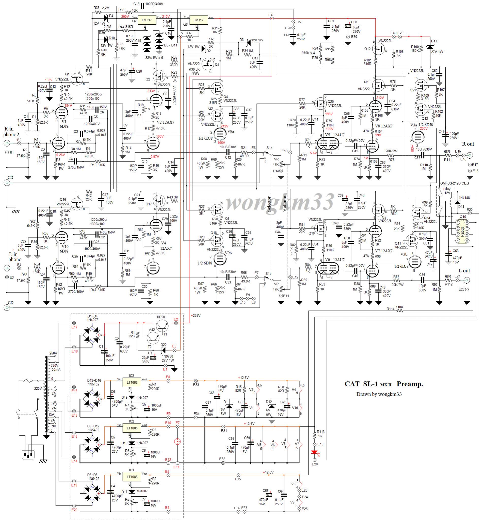
So complicated. Maybe the top half of 12AX7 acting as an active load is just an excuse to bring the voltage up slowly since it's direct coupled to the cathode follower. I wonder what it would sound like with a resistor load or in the line stage not use the 12AX7 at all and reconnect the unused half of 12AU7(what a waste!) as the second stage. The least they could do is to make it able to alternate the 12AU7 halves for each channel so after up to mileage user can swap the tubes for fresh halves (Artemis Labs preamp did the same thing). I understand it was a trend in that era not to invert the phase so they had to resort to two gain stages before cathode follower. A grounded grid circuit would solve the problem of too much gain and keeping it in phase and easier use of feedback.
Hi Oneminde
Thanks a lot for tracking and uploading schematics and parts layout. I am in the process of attempting to rectify an SL1 mk2 which blew the 317 regulators and checking to see if the mosfets have survived.
By the way did you manage to compare the SL1 to the RTP3D? Would be interested in knowing your views as I think these are classics
I have not been able to build anything yet, but hopefully that will change. I am in the planing processes of my own Babelfish XA252 (aka Zen's version of the PASS XA25).

YES , I DID ITReference pictures or did you make it ?
I know this is an old thread, but it seems the closest I have found to good information on this piece. MK2 version SL1 SN: 6064 The unit I am working on has a constant noise on both channels. I have replaced the tubes, with no change. The Power Supply has a burnt resistor R5 does anyone know the value it is supposed to be?
You may have some burned small mosfet all over the place, and even burn small LM 317 regulators. These small regulators are part of the Maida stype HV Regulator, should be ok if they are floating on the HV, but they are very fragile and get burn easily if anything goes wrong on the HV… I know I fixed a few. On my own version I ended up replacing the Maida regulator with a nice, slow start HV shunt regulator. It is much better, has lower noise and the slow start protect the small Mosfet.
With the power off, and any HV drain off! you can check the small mosfet, if the are short between Drain and Source, well they are dead and need replacement.
The small LM317 shouldn’t be short between an In and Out pins for obvious reason. Also in circuit, with the HV on, you should measure lower voltage at the Out pin than the In pin…
Keep in mind there is a long string of zener reference for the LM317 Q7. I saw also some unit with shorted zener that caused incorrect reference voltage.
Finally the original pcb is fragile, with small part pads, easy to damage when desoldering. Work with care on it.
SB
Last edited:
Thank you for the advice on this. I replaced R5 with a 1K ohm. It measured 400 when burnt. At turn on, I see 2.5Vdc across it, but it goes to 0 after a minute or so. I did not measure any shorted parts. I will have to re-visit that, because the unit still makes the noise at the output. I measure 250Vdc across the supply caps in the preamp chassis. Making measurements in the PS chassis is kinda tricky as it is a tight area.
- Home
- Amplifiers
- Tubes / Valves
- DIY CAT SL1 preamp