Hi DT,
I'd want to rewire these so that pin 3 when to the RCA shield and the ground was open circuit at this end. The chassis' will be connected through the ground on the mains connection.
-Chris
I'd want to rewire these so that pin 3 when to the RCA shield and the ground was open circuit at this end. The chassis' will be connected through the ground on the mains connection.
-Chris
Hi DT,
I'd want to rewire these so that pin 3 when to the RCA shield and the ground was open circuit at this end. The chassis' will be connected through the ground on the mains connection.
-Chris
Chris,
This is what I am doing.
Cut a 6 foot long XLR cord in half a solder an rca on the end of each of the two pieces. The result is two 3 foot long cables each with an rca soldered on the cut ends. One with a male XLR and the other with a Female XLR, a input and output pair. Or double this for four cables for 2 channels.
GlS makes quality built products. I have a bunch used for a balanced Tri-amp theater system.
GLS Audio 24K Gold RCA Plugs and Connectors - 8 Pack
GLS Audio XLR-M to XLR-F Patch Snake Cables - 6ft Colors - 6 Pack
DT
is this GLS cable a coaxial?
Pin2 takes the core
Pin3 takes the screen/shield
Pin1 also takes the shield and the XLR shell.
Why do we need to connect the screen shield of the RCA's return to the chassis of the XLR socket/plug?
Pin2 takes the core
Pin3 takes the screen/shield
Pin1 also takes the shield and the XLR shell.
Why do we need to connect the screen shield of the RCA's return to the chassis of the XLR socket/plug?
Use the positive phase for signal, and the negative phase (180°) for the common RCA ground. You do the same with measuring the output if the amplifier. That should break the loop nicely.
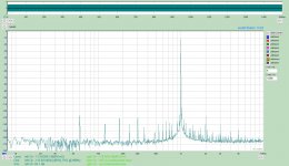
Ok, tried that. See attached plot.
The blue curve is with the amplifier input shortened (only connection between RTX and amp is via speaker output to RTX input).
The red curve is with a standard XLR-to-RCA converter, as described in my previous post 1675.
The green curve is using your setup (XLR-HOT to RCA-PIN, XLR-COLD to RCA-RING, no GND/chassis connection).
I thought your suggestion was a good one, because it avoids the additional connection of the chassis/GND of the RTX and the amplifier. I expected this would reduce the hum/noise in the measurement as compared to the setup using the standard XLR-to-RCA converter. However, it was the other way round. Why?
I'd really like to understand how the hum/noise creeps in, and how I can deal with it. With the amp input shortened (amp input not connected to the RTX output), there is much less hum/noise.

Last edited:
There is a very informative "pdf" from 2012, some of you may be aware of that.
Search for: An Overview of Audio System Grounding & Interfacing (by Bill Whitlock, President
Jensen Transformers, Inc.) (indy-aes-2012-seminar-w-notes-v1-0.pdf)
Search for: An Overview of Audio System Grounding & Interfacing (by Bill Whitlock, President
Jensen Transformers, Inc.) (indy-aes-2012-seminar-w-notes-v1-0.pdf)
Last edited:
Are you confirming that connecting the XLR chassis (pin1) to the RCA screen/shield measures quieter?Ok, tried that. See attached plot.
The blue curve is with the amplifier input shortened (only connection between RTX and amp is via speaker output to RTX input).
The red curve is with a standard XLR-to-RCA converter, as described in my previous post 1675.
The green curve is using your setup (XLR-HOT to RCA-PIN, XLR-COLD to RCA-RING, no GND/chassis connection).
I thought your suggestion was a good one, because it avoids the additional connection of the chassis/GND of the RTX and the amplifier. I expected this would reduce the hum/noise in the measurement as compared to the setup using the standard XLR-to-RCA converter. However, it was the other way round. Why?
I'd really like to understand how the hum/noise creeps in, and how I can deal with it. With the amp input shortened (amp input not connected to the RTX output), there is much less hum/noise.
View attachment 659201
How is the KT66 connected?...........................I'd really like to understand how the hum/noise creeps in, and how I can deal with it. With the amp input shortened (amp input not connected to the RTX output), there is much less hum/noise.
View attachment 659201
Do you get similar results with another amplifier?
What if the other amplifier is not directly connected to the mains Protective Earth? i.e. use a Disconnecting Network between Main Audio Ground and protected Chassis
I was just trying to convert RXT input to RCA using an adapter and discovered that it’s connector latch is grounded so the adapter won’t work as originally expected. Guess I need to make a custom made adapter.
I'd really like to understand how the hum/noise creeps in, and how I can deal with it. With the amp input shortened (amp input not connected to the RTX output), there is much less hum/noise.
Not at 50 Hz, but at low multiples of 2*50 Hz.
Could it be that the symmetry of a rectifier helps there?
Just speculation.
Gerhard
I've lifted the connections to pin 1 on the cables I've purchased, so far that has worked fine.
Other than lots of goofy loop back stuff the only practical thing I have done so far is to measure playback response in my strain gauge cartridge and pre-amp combo. It worked very well.
It is a huge, huge, huge (did I say huge) improvement over the old sound card set up using the same software.
Other than lots of goofy loop back stuff the only practical thing I have done so far is to measure playback response in my strain gauge cartridge and pre-amp combo. It worked very well.
It is a huge, huge, huge (did I say huge) improvement over the old sound card set up using the same software.
On the XLR to anything else what I do is break out pin one to a separate wire to connect to the chassis. Pins 2 & 3 are then a differential input to the RTX. The separate pin 1 chassis ground allows connection to the chassis without sharing ground currents with the differential pair. Often I find moving the ground around chassis connection points makes a big difference in powerline residual. Its tedious and usually not necessary when the signals you are looking for are above -80. Essential when they are at -120 dB or lower.
Use the BNC out on the RTX for single ended loads. There is a circuit for making the output auto adjust if the balanced out connects to a single ended input but it brings a lot of overhead, especially when driving low Z loads. I tried it for a 50 Ohm output Z and I needed big power resistors for it to work.
The RTX is a balanced 100 Ohm source (means 50 Ohms in series with each output). The Low Z insures that the signal is not loaded by load capacitance or load nonlinearity.
One big change i would push for on a next gen RTX is ground isolation of the source and the input. Mostly not hard since they are all isolated from the digital except for the extra supplies.
I bought a handful of cheap ones on eBay for this. Easy to chop up. One useful trick is to remove the latches on the connectors. For test connections they are a nuisance.
Are you confirming that connecting the XLR chassis (pin1) to the RCA screen/shield measures quieter?
Yes, that measures a wee bit quieter than without the chassis connected.
How is the KT66 connected?
Do you get similar results with another amplifier?
What if the other amplifier is not directly connected to the mains Protective Earth? i.e. use a Disconnecting Network between Main Audio Ground and protected Chassis
The K66 amplifier input was either shortened or connected to the RTX output in one of the two ways as described in my previous post. The amp output was connected to an 8 Ohm dummy load. The RTX input (balanced / hot and cold) was connected across this dummy load, and the chassis pin of the RTX input XLR was left unconnected. The audio GND of the amp is connected to the chassis via a ground loop breaker (diodes/bridge rectifier plus 10 Ohm resistor). The chassis is connected to safety earth via a three-pronged mains cable.
I didn't have another amp with a three-pronged mains cable, but I'll go and find one.
What happens with the RTX output from the NEGATIVE/COLD pin?
If the standard XLR-to-RCA adapter is used, the NEG is grounded to the RTX chassis, which is directly connected to safety earth.
If the custom cable is used (XLR-POS to RCA-PIN and XLR-NEG to RCA-RING, no GND connection), the NEG output is connected to the audio GND of the amp, which connects to the safety earth via the ground loop breaker. What happens there? Could this somehow explain why the measurement with the custom adapter gives slightly more noise than with the standard XLR-to-RCA adapter?
Thinking a bit further, would an isolation transformer in the mains power line of either the RTX or the amp (or other DUT) help to break the ground loop via the safety earth connection?
Not at 50 Hz, but at low multiples of 2*50 Hz.
Could it be that the symmetry of a rectifier helps there?
Just speculation.
Yes, the difference with the input shortened is strongest for 100 Hz, 200 Hz, etc., which smells like PSU ripple from a rectifier. I don't see how this would arise just from connecting the RTX output to the amp. The only thing I can think of is maybe residual PSU ripple showing up at the RTX output, which is then amplified by the amp and then shows up at the speaker output... is this a possibility? What are the voltage amplitudes of the residual PSU ripple at the RTX outputs, if any?
Hi Demian,
I also clip the pin 1 connection to shield and just input to the RTX as a balanced connection. As for the input to the D.U.T., Pin 2 is used with the shield as the common connection. It's always worked in audio that way, and on the test bench.
-Chris
I also clip the pin 1 connection to shield and just input to the RTX as a balanced connection. As for the input to the D.U.T., Pin 2 is used with the shield as the common connection. It's always worked in audio that way, and on the test bench.
-Chris
mbrennwa,
For a floating single end DUT you may get away with using the RTX XLR connectors and not get into the grounding wire wars.
The DUT you are testing is single ended. It is grounded.
For single ended DUT’s AP recommends using the single end BNC connectors with BNC cables with BNC to RCA adaptors to connect to the single end DUT.
“…we recommend 75Ω (RG-59/U) cables from a reputable manufacturer like Pomona Electronics. These cables will provide years of trouble free service. For connecting the BNC cables to the RCA outputs on the device, use good quality BNC female to RCA plug adapters.”
Recommended Cables for Unbalanced Audio Testing - Audio Precision
DT
Last edited:
If you use the balanced output and tie the negative pin to ground on the DUT, if the amp is floating then the amp chassis will be moving with the audio something that creates a lot of common mode. If the amp chassis is grounded or returns to the RTX common then you are shorting out one output. Not the best way to test. If you leave the negative output floating and tie pin 1 to the chassis it should all work well.
Hello,
No one is talking to each other.
JensH is recommending cable #17 in the Rane Note. The shield is only connected to pin 1 nothing else.
Audio1 you have the shield/pin1 connecting to the DUT chassis ground, if the DUT is floating there is no ground. Ground is that cold damp concrete floor under your bare feet. My DUT is on a wood breadboard inside a 12”x 14”x 6” steel box bonded to the earth connection on the analyzer.
I think that there is work needed to get everyone on the same page.
DT
he DUT you are testing is single ended. It is grounded.
For single ended DUT’s AP recommends using the single end BNC connectors with BNC cables with BNC to RCA adaptors to connect to the single end DUT.
I have tried the BNC out vs. the XLR-to-RCA adapter. It did not make a difference. Why would it?
No one is talking to each other.
I think we are "talking" to each other. But I agree that it is sometimes hard to understand some of the comments, because they are missing the context. Replies / comments to earlier messages are so much easier to understand if (parts of) that previous message is quoted.
JensH is recommending cable #17 in the Rane Note. The shield is only connected to pin 1 nothing else.
I know, and that's what I tried (as described). On a somewhat semantic note, I'd like to suggest Rane #6 instead of #17, because the XLR is at the output (or the RTX) and the RCA is on the input (of the amp); but yes, it's the same cable, just backwards.
I think that there is work needed to get everyone on the same page.
Yes. Yes. Yes. Yes. Yes. Yes... (I belive you get my point). Yes!
The page actually exists! It's here, as described a few posts back. It would be great if all of you would add their knowledge to this page. Please do!
If you are telling you analyzer to output 1 volt in balanced mode that is 1 volt P to P across the minus and plus pins, that shows up on the FFT plot as 0dBV.
If you are telling you analyzer to output 1 volt in balanced mode and you connect it Plus pin to shield that is only 0.5 volt P to P. On the FFT plot that shows up as -6dBV. (negative is floating)
You have lost 6dBV, you may think that is a improvement on the noise floor.
Using the balanced connection and a RCA adaption you can connect it the way you did the 6dbV will not be lost. Do it as Audio1 suggests the negative output is floating. it may work out well testing and noise wise. the connection is single end with a apparent balanced XLR output. However 0.5 volts or 6dBV is MIA.
It is easy to make a cognitive error.
Why not follow the AP recommendation of using the single end BNC output and cable?
DT
- Home
- Design & Build
- Equipment & Tools
- DIY Audio Analyzer with AK5397/AK5394A and AK4490