This is very good option Focusrite Scarlett: https://us.focusrite.com/usb-audio-interfaces/scarlett-2i2
Hi Tesla Audio,
I wouldn't say so. It has very limited frequency range. Otherwise, it looks good.
This is intended as a recording device, the instrument part is an afterthought.
-Chris
I wouldn't say so. It has very limited frequency range. Otherwise, it looks good.
This is intended as a recording device, the instrument part is an afterthought.
-Chris
Anatech,
it is 192kHz device. Of course it's not good for laboratory measurements but for most diy users should be enough.
it is 192kHz device. Of course it's not good for laboratory measurements but for most diy users should be enough.
Anatech,
it is 192kHz device. Of course it's not good for laboratory measurements but for most diy users should be enough.
I agree. In fact the little brother that goes for $99 US looks very good as well.
https://us.focusrite.com/usb-audio-interfaces/scarlett-solo
Hi Tesla Audio, Carl,
I disagree completely. You have to look above 20 KHz to see what's going on up there. I'd say that 100 KHz would be a minimum, or as close as you could get.
Look at all the folks using Non-Oversampling DACs. I would think that 44.1 KHz would be a critical thing to look at. You've got to make certain that your instrumentation isn't lying to you. By stopping at 20 KHz, it is almost guarantied to lie it's little display off. Even back in the 70's, you had to make sure the bias oscillator (normally 95 to 105 KHz) wasn't getting loose into your gear.
I'm sorry, but I feel that accepting 20 KHz as a reasonable limit is just sticking your heads in the sand. But I guess you'd feel pretty good not knowing why your output stage was getting so hot!
-Chris
Hi Tesla Audio, Carl,
I disagree completely. ... But I guess you'd feel pretty good not knowing why your output stage was getting so hot!
-Chris
Ha, ha ...
Make nice Chris! You make a valid point. But can you name a commercial preamp out there meets your requirement?
I confess that I was falling back on my habit of making room measurements more often than gear measurements. I have an aging AP bench box that I use for gear measurements.
Last edited:
The project is progressing, but still at a relatively slow pace.
I have got the first set of mechanical parts and the first unit has been assembled. The purpose was mainly to check that the mechanical parts were as they should be. They are quite close, but I need to make a few adjustments before we are ready to make mechanical parts for the prototype series. No major changes, just some fine-tuning.
I hope that I can post a few pictures tomorrow.
Hi Carl,
Did you mean sound card, or preamplifier?
Many preamps will reproduce very high frequency signals, and 44.1 KHz is really still within the pass band of all but the cheapest. Many amplifiers wouldn't have a problem with this either, but their zobels would.
All the sound cards I currently use will reproduce 80 some-odd KHz. I've used them with one of those software programs for that purpose. They don't reach 100 KHz, but they are convenient for a quick check. Still, for troubleshooting I use a spectrum analyzer to get answers. I have an HP 35665A that reaches 102 KHz in single channel mode, and an HP 3585A that reaches 40 MHz.
The dangers of incomplete coverage don't come from our direction. They come from hobbyists trying to do a good job but without the knowledge that tells them to believe these results without checking further. These are the people without an oscilloscope to fall back on. I would be careful about what instrument I give the nod to for them.
Doing speakers or rooms? 20 KHz might be enough, but a little higher would be better. For pieces of electronic equipment, I just think their only instrument should give them as much of the truth as reasonably possible. At least they should always be aware of the shortcomings of budget instruments.
-Chris
Did you mean sound card, or preamplifier?
Many preamps will reproduce very high frequency signals, and 44.1 KHz is really still within the pass band of all but the cheapest. Many amplifiers wouldn't have a problem with this either, but their zobels would.
All the sound cards I currently use will reproduce 80 some-odd KHz. I've used them with one of those software programs for that purpose. They don't reach 100 KHz, but they are convenient for a quick check. Still, for troubleshooting I use a spectrum analyzer to get answers. I have an HP 35665A that reaches 102 KHz in single channel mode, and an HP 3585A that reaches 40 MHz.
The dangers of incomplete coverage don't come from our direction. They come from hobbyists trying to do a good job but without the knowledge that tells them to believe these results without checking further. These are the people without an oscilloscope to fall back on. I would be careful about what instrument I give the nod to for them.
Doing speakers or rooms? 20 KHz might be enough, but a little higher would be better. For pieces of electronic equipment, I just think their only instrument should give them as much of the truth as reasonably possible. At least they should always be aware of the shortcomings of budget instruments.
That was supposed to be humor. I can see why it didn't come across that way. Sorry.But I guess you'd feel pretty good not knowing why your output stage was getting so hot!
-Chris
Hi Carl,
Did you mean sound card, or preamplifier? ...
That was supposed to be humor. I can see why it didn't come across that way. Sorry.
-Chris
I knew that you were just poking at us. No offense taken. Your points are all valid. Soundcard is undoubtedly a better description, but as for room measurements I am not aware of any room measurement software that gathers samples above 20kHz.
Hi Carl,
I didn't know that. I thought there might be some interesting stuff going on up to 30 KHz. You could tune those old rod remote controls from the 60's with it. 🙂
-Chris
I didn't know that. I thought there might be some interesting stuff going on up to 30 KHz. You could tune those old rod remote controls from the 60's with it. 🙂
-Chris
I agree. In fact the little brother that goes for $99 US looks very good as well.
https://us.focusrite.com/usb-audio-interfaces/scarlett-solo
I bought one of these a couple of years back. Very good VFM, its mic preamp is definitely good enough for room measurements.
But, beware that it has no stereo line in.
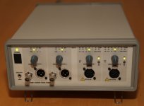
Here are a couple of pictures of the first prototype in an enclosure.
The front foil is still not in the right material. It was made to get an impression of what it would look like, to find out if anything needs to be changed. There will be some minor changes like font-size and a couple of other things.
The LED indicators will be improved to avoid light-bleed from one LED to the next one.
I still haven't got the right mains switch, so another one was used here until I get the proper one.
Attachments
Here are a couple of pictures of the first prototype in an enclosure...
That looks very nice to me!
Wow! That looks great! There is an huge amount of work required to get all the bits and pieces together so they fit together like that. Kudos!
Hi Jens,
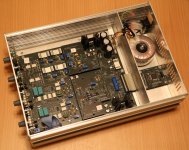
Is that an all metal case? If not, does it have an inner shield?
Visually it looks great.
-Chris
Is that an all metal case? If not, does it have an inner shield?
Visually it looks great.
-Chris
It is an all metal case. Except for the frames around the front and back and the plastic/rubber feet.
I may also add shields over the input amplifiers. The PCB has been prepared for that.
I may also add shields over the input amplifiers. The PCB has been prepared for that.
Hi Jens,
Perfect! Shields over the input amplifiers probably should go in too. You sound like you're on the road to creating a classic.
-Chris
Perfect! Shields over the input amplifiers probably should go in too. You sound like you're on the road to creating a classic.
-Chris
I still haven't got the right mains switch, so another one was used here until I get the proper one.
For my personal taste, the main switch could/should be at the back side to avoid power cable radiation into the box, while we deal here with uV or lower voltage. May also an additional main filter is a choice.
May also made clear enough for tube gear tester: The maximal allowed DC!
An other question: Where are the master crystal clocks located. In case some would like to have a better master clock with lower phase noise.
just my 2 cents
Hp
The mains switch IS at the back side. But the control is from the front. So no mains cables are going through the compartment with the generator and analyzer.
I would like to avoid using a mains filter, because typically they couple a lot of noise from the mains into the chassis and this can cause additional noise issues.
At the moment I use 250 V DC capacitors on the inputs (Polypropylene).
The crystal oscillators are placed between the ADC board and the DAC board. I use NDK oscillators with very low phase noise/jitter. It is possible to disable the internal oscillators and use an external oscillator (connected to the unused IDC connector), but I am not sure if there is anything to gain here in terms of phase noise. It is primarily intended for getting a clock from an external source, in case of synchronizing to an input on a digital I/O extension.
- Home
- Design & Build
- Equipment & Tools
- DIY Audio Analyzer with AK5397/AK5394A and AK4490