I recall trying to select resistors from a batch/tape of 1% - many had similar tempco, but a significant percentage went the other way - and I think they were general +/-100ppm/C. Always some doubt about common tolerance parts and if the 'better' parts coming off the line have been sorted out from the mass.
In any event, due to what you are trying to achieve ... This is experimental. You're going to have to characterize whatever you end up with. Rolling your own should be less expensive and an exact ratio for division isn't as important as long as it is linear. Each "probe" would be on it's own PCB to make the temperature effects identical (as opposed to everything on one PCB).
I think that saving a couple dollars on resistors isn't nearly as important as ending up with something linear. If you can rent the probes you are thinking about, it gives you a chance to test them with minimal outlay, if they are good then buying those is a very good option since they are already packaged and a known quantity.
Don't forget to run the signal for a longer time so you can chart thermal changes in whatever you end up with.
... and that they're at the same temperature. Which they likely won't be. If you lay them out side-by-side the ones in the middle will run hotter. If you lay them out end-to-end, the ones on the end will have a different thermal resistance to the outside world, so they'll have different distortion.Although that assumes all 10 resistors have identical tempco's and voltage related distortion.
Perfect matching doesn't exist in real life. And given that we can get down in the -150 to -160 dBc THD range with the current technology, I'd say there's no need for perfect matching either.
Tom

Pfft. I'd be more than happy if I could get down to 0.001% residual from the attenuator (-100 dBc). In my test (post 3256) the resistor attenuator added 0.02% to the THD measurement.we can get down in the -150 to -160 dBc THD range
Yup. But what exactly does that mean? Characterize what, how? And then how do I compensate the raw measurement to give me the DUT distortion only?You're going to have to characterize whatever you end up with.
Hi mbrennwa,
Well, it means starting from signal sources that you know and watching what possible impairments you get with your divider. Your high voltage signal source is an unknown. You are doing something new, uncharted waters to the best of my knowledge.
Once you get the AC response from known, lower voltage sources, you can follow calibration lab procedures to look at a DC source, varying in level with a very accurate DVM (HP 3458A being the gold standard). Compare direct readings as high as you safely can with your divider readings to see if they are linear. If your readings remain perfectly linear, chances are they may continue to be. This is an assumption of course. Experimental error is also a factor. If you have the actual calibration readings from the 3458A (or whatever) you can see it's linearity as long as the lab calibrated DC standard is highly accurate.
Once you have something that looks linear, check your electrostat amp at voltages you were able to generate with normal amplifiers, then increase the voltages and plot what you get. The problem is, you have two unknowns. Most AC lab sources are not low distortion, not to our levels. But you can infer the DC readings. You need to watch the initial reading, then watch at that level to see what, if any changes occur in the reading. This would be a temperature (most likely) or voltage coefficient change. Voltage coefficient changes should be immediate, without a time component.
If you do create something that looks to be linear, the final step would be to send it in to an accredited calibration lab to have it certified. They would supply the accuracy limits of their calibration constants.
mbrennwa, perhaps one approach could be to compare a 100:1 probe, with say four dividers of different constructions - such as a 100:1 divider made from circa 0.25W resistors of 10M and a 1 Meg, and from 3M3 and a 1Meg, and another two dividers using 1-2W resistors of same resistance. The rms voltage across resistors is different, and the temperature rise is different, so may clearly show up THD improvements/differences, and then act as a benchmark for further probe comparisons.
I guess you could use REW and an RTX6001 to null any probe related residual harmonics for simple single frequency testing, but 10:1 and certainly 100:1 loopback may be the concern due to loopback noise floor.
I guess you could use REW and an RTX6001 to null any probe related residual harmonics for simple single frequency testing, but 10:1 and certainly 100:1 loopback may be the concern due to loopback noise floor.
I thought about this, too. I am a bit hesitant because I found both the 1:100 probe and the resistive voltage dividers to add harmonics to the result. So I'd be comparing two unknowns to each other.perhaps one approach could be to compare a 100:1 probe, with say four dividers of different constructions...
The loopback idea is interesting. I could use two identical probes: one for the DUT and one for the loopback. I believe most software uses the loopback to deconvolve the DUT signal from the loopback signal in order to compensate for gain, time delays, and imperfections in the frequency response of the sound card. However, the deconvolution inherently assumes a linear system, and I am not sure if/how deconvolution would play out with compensating non-linear distortion effects by referencing the DUT signal by the loopback.I guess you could use REW and an RTX6001 to null any probe related residual harmonics for simple single frequency testing, but 10:1 and certainly 100:1 loopback may be the concern due to loopback noise floor.
I just had a (maybe weird) idea...
So I want a capacitive dummy load of 100 pF for testing of my electrostatic amp. The bipolar 1 kHz AC output from the amp into that dummy capacitor would be up to 1.6 kVpp, or 570 Vrms(sine).
What happens if I replace the 100 pF dummy by a C-R-C series connection, with C = 200 pF and R = 1 kOhm? This modified dummy load would still be sufficiently close to a pure 100 pF load at audio frequencies. Most of the voltage drop would still be on the Cs, while the voltage across the R would be much smaller. The attachment shows the theoretically calculated voltage drop across the R. I could simply measure this voltage across R using the RTX. The fundamental at 1 kHz would be strongly attenuated, while the harmonics would be less attenuated (6 dB/octave). I could simply subtract the high-pass effect from the measured harmonics to compensate for the R-C high-pass.
I am pretty sure I am missing a few things here, and some might turn out to be roadblocks. Thoughts?
Try it and see. It's a good thought.
If you depart from a straight line, you have issues somewhere, but at least you know and can look at things from there. The only real issue I see is frequency stability. That would obviously change the impedance of your capacitors.
If you depart from a straight line, you have issues somewhere, but at least you know and can look at things from there. The only real issue I see is frequency stability. That would obviously change the impedance of your capacitors.
I would think the frequency of the fundamental (and hence also the harmonics) should be quite stable at the output of the RTX. If not, the impedance change of the caps will apply to the voltage levels of the fundamental and the harmonics in the same way, so the harmonic levels relative to the fundamental will not be affected.
If the R has non-linear resistivity against high voltage - does C have a linear one? IIUC the plan would trade impedance for resistance, but is C impedance vs. high voltage linear?
Frequency of RTX (proper crystal, no analog oscillator) is definitely stable enough for a stable capacitance divider, since my distortion compensation (based on measuring parameters of an RC filter) fixed the RTX output distortion by over 20 decibel https://www.diyaudio.com/community/...ion-for-measurement-setup.328871/post-6287064
Frequency of RTX (proper crystal, no analog oscillator) is definitely stable enough for a stable capacitance divider, since my distortion compensation (based on measuring parameters of an RC filter) fixed the RTX output distortion by over 20 decibel https://www.diyaudio.com/community/...ion-for-measurement-setup.328871/post-6287064
My thought of using more than one resistive divider is to identify a trend in lower harmonic levels from using (a) lower voltage across each divider resistor, and (b) lower temp rise within each divider resistor. Yes there is still an unknown, but if a particular configuration of divider demonstrates lower harmonic contributions, then that seems to be a simpler form of benchmark for comparing probes.I thought about this, too. I am a bit hesitant because I found both the 1:100 probe and the resistive voltage dividers to add harmonics to the result. So I'd be comparing two unknowns to each other.
The loopback idea is interesting. I could use two identical probes: one for the DUT and one for the loopback. I believe most software uses the loopback to deconvolve the DUT signal from the loopback signal in order to compensate for gain, time delays, and imperfections in the frequency response of the sound card. However, the deconvolution inherently assumes a linear system, and I am not sure if/how deconvolution would play out with compensating non-linear distortion effects by referencing the DUT signal by the loopback.
The aspect of REW I was thinking of was the 'Add harmonic distortion' feature in the Sine generator of the Tones generator menu. For a known loopback hardware and tone level/frequency, the loopback harmonic levels can be suppressed into the noise floor, such that subsequent inclusion of a DUT allows just the DUT contribution to be measured. However I can see that loopback harmonic compensation for the probe should be done at the signal level of interest for the probe, which is not simply available from a loopback, and rather implies that you have a 'blameless' amplifier in the loop. That catch-22 may be somewhat alleviated by using a low distortion probe (as per first paragraph) and your DUT amp to form a loopback with suppressed harmonics to then cross check probe performance.
Just thinking of ways to lower the 'harmonic floor' of such a test setup 🙂 . This had me thinking of how I would go about checking a measurement scenario where I need to use my 100:1 probe and need to suppress concerns from probe distortion (somewhat similar to when loads are being checked for their inherent distortion contribution to a low HD measurement).
I wonder whether distortions of the RTX generator are negligible for measuring distortions of the high-voltage divider. Are they?

It would be possible to determine distortions of the [ generator ] and of the [ DUT=amp + HV divider + analyzer ] parts, using the distortion-splitting technique, because the required attenuator and RC filter between the generator and the DUT=amp would run at low voltages (i.e. at negligible distortion). Then considering the analyzer distortions negligible (which they probably are) we could say the latter distortions are those of the [ DUT + divider ].
But I have no idea how to split the DUT vs. HV divider distortions at those high voltages as the calibrating attenuator and RC filter would distort just like the measured HV divider and their contribution to the overall distortions could not be ignored.
I was lucky enough to find some high-voltage 1000:1 attenuators from an HP high voltage calibrator.
It was a thick-film resistor 'plate' with a 1/1000 tap mounted in a steel box rated for 1kV flat to 100kHz.
But that was a lucky find, allowing me to directly connect the AP to the stators.
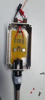
Before that I purpose-build a balanced hv attenuator for direct measuring on the stators. The trick is to design a measurmenet system.
The series element was designed with the needed attenuation with the expected load (in this case the 100k from thge AP with ~150pF).
Used a specific balanced XLR cable to the AP and accounted for the load impedance and capacitantance with some parallel trimmers, see pic.
Put a big label on the box and the cable to be sure that always the same cable was used!
Jan
It was a thick-film resistor 'plate' with a 1/1000 tap mounted in a steel box rated for 1kV flat to 100kHz.
But that was a lucky find, allowing me to directly connect the AP to the stators.
Before that I purpose-build a balanced hv attenuator for direct measuring on the stators. The trick is to design a measurmenet system.
The series element was designed with the needed attenuation with the expected load (in this case the 100k from thge AP with ~150pF).
Used a specific balanced XLR cable to the AP and accounted for the load impedance and capacitantance with some parallel trimmers, see pic.
Put a big label on the box and the cable to be sure that always the same cable was used!
Jan
Attachments
Last edited:
Once you realize it's not audio but basic engineering, windows open up 😎
Jan
Jan
A capacitive divider can work fine if the load is pure capacitance or mostly capacitance. A 1000:1 ratio with the series cap as 100 pF would have the load as .1 uF. The 100K would be matched with 100 MegOhms or essentally nothing. You would need a good 100pF cap good for over 1 KV at 20 KHz +. Maybe make it with a glass tube with foil on the outside and inside? Or this might work: https://www.ebay.com/itm/364857989222?_skw=100+pF+capactor&itmmeta=01JPRTEK6X5DR8S6S2TPR1X645&hash=item54f33b1866:g:sZgAAOSwZ49mKLph&itmprp=enc:AQAKAAAA8FkggFvd1GGDu0w3yXCmi1eSROafLhEKzF1Q+ZAzjWrjzmHeK/uztCFaSKVzvLx6WpgGDoMnU04xQLFvMyMri1Ec1iRy7YSaDTDNvAwZtNDy7sIwAFWCiXjvLMTYCW/ICN98wYeKQfdTomtoNTWVpWu16Fh1as+dlZ2pGaeqLvra4RuOYDJ3PutVgQI9I6c50VA8uREQONKuhYEJJtGJdODsnPm+z4/+oTK14Ls3GXdYDzW+9cNsL9eaiuLFCzw4/H3yR0YwSIA444CCBivEQnVEmO/YPCL3lPuYWO5dUOO/FzvTXoUE9ehMzDt5zyB5CQ==|tkp:BFBMnrW6mrZl
Or 4 of these https://www.ebay.com/itm/2935985893...BgM9FjwO2vwPMHO8o19z4cU18=|tkp:Bk9SR9j71Jq2ZQ in series/parallel. Mica caps are usually very low distortion. PM me if you want some 100 Meg resistors.
Or 4 of these https://www.ebay.com/itm/2935985893...BgM9FjwO2vwPMHO8o19z4cU18=|tkp:Bk9SR9j71Jq2ZQ in series/parallel. Mica caps are usually very low distortion. PM me if you want some 100 Meg resistors.
Last edited:
So I'd load the amplifier output with three caps in series, configured as a C1-C2-C1 voltage splitter with C1 = 0.1 uF and C2 = 100 pF? I also thought about this. But what happens with the input impedance (resistance+capacitance) of the RTX that will be in parallel to the C2 = 100 pF? This would need compensation across the C1 parts. Another option would be to connect an opamp or instrumentation amp across C2 to decouple the RTX input from C2. However, I'd like to keep things simple. Would like to avoid yet another rabbit hole if possible.A capacitive divider can work fine if the load is pure capacitance or mostly capacitance. A 1000:1 ratio with the series cap as 100 pF would have the load as .1 uF.
This is why I thought of loading the amp with a Cx-R-Cx splitter, where Cx = 200 pF and R = 1 kOhm. The 1 kOhm would be much lower than the RTX input impedance, so the RTX input would not affect the voltage splitter very much. I wonder if (or how much) the Cx would add any distortion to the measurement result.
Not sure what this refers to. Which 100k and 100M resistors are you talking about?The 100K would be matched with 100 MegOhms or essentally nothing.
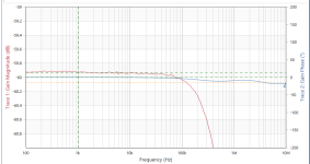
This is what I see on the resistor between the two caps if the amp output is a clean sine. Looks like something is not going well with my C-R-C idea...Try it and see.
- Home
- Design & Build
- Equipment & Tools
- DIY Audio Analyzer with AK5397/AK5394A and AK4490