I tested arm/cartridge resonance again by using three different methods.
Method 1.
This method is my own creation. I ripped two tracks from Cardas Frequency Sweep record. One is 65.4 Hz lateral modulation and another is 65.4 Hz vertical modulation. In Audition’s spectrum analysis, both frequencies indicated that arm/cartridge resonance were in 3-4 Hz areas.


In order to find peak amplitudes for both tracks, I deleted all information above 50 Hz in Audition. At the peak amplitudes, the lateral resonance frequency is 4 Hz and vertical resonance frequency is 3.4Hz.


In this method, the turntable worked normally so speed and friction were irreverent because nothing was changed.
Method 2.
This method was posted by John Elison at Vinyl Asylum, too.
Yet another way to measure arm/cartridge resonance... - John Elison - Vinyl Asylum
Here is the result. This resonance is vertical resonance frequency because how the test is carried out.

The vertical resonance frequency is 4.2 Hz under this method.
Method 3.
This method is same as I used before, but I refined measuring method. I deleted all useless information around resonance areas and found peak amplitudes.


The lateral resonance frequency=3.4 Hz, the vertical resonance frequency=4.3 Hz
In summery, all three methods show that lateral resonance frequencies and vertical resonance frequencies are pretty consist under different testing methods.
Method 1.
This method is my own creation. I ripped two tracks from Cardas Frequency Sweep record. One is 65.4 Hz lateral modulation and another is 65.4 Hz vertical modulation. In Audition’s spectrum analysis, both frequencies indicated that arm/cartridge resonance were in 3-4 Hz areas.
In order to find peak amplitudes for both tracks, I deleted all information above 50 Hz in Audition. At the peak amplitudes, the lateral resonance frequency is 4 Hz and vertical resonance frequency is 3.4Hz.
In this method, the turntable worked normally so speed and friction were irreverent because nothing was changed.
Method 2.
This method was posted by John Elison at Vinyl Asylum, too.
Yet another way to measure arm/cartridge resonance... - John Elison - Vinyl Asylum
Here is the result. This resonance is vertical resonance frequency because how the test is carried out.
The vertical resonance frequency is 4.2 Hz under this method.
Method 3.
This method is same as I used before, but I refined measuring method. I deleted all useless information around resonance areas and found peak amplitudes.
The lateral resonance frequency=3.4 Hz, the vertical resonance frequency=4.3 Hz
In summery, all three methods show that lateral resonance frequencies and vertical resonance frequencies are pretty consist under different testing methods.
Hi Jim, ooops I double checked on the 3150Hz files you posted, and confirm they do show both lateral and vertical resonances near 4Hz. I must have picked up the wrong file to run the spectrum analysis, easily done, apols. The polar plots are definitely right though !
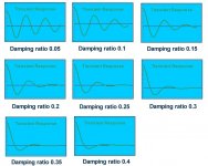
Of those methods, the logarithmic decrement can also deduce the damping ratio which is really the elephant in the room and no-one ever talks about.....
In this case, damping ratio works out slightly less than 0.1, perhaps 0.08 or so, which is fairly typical IME, and generally a bit skinny. IMO, about 0.15 is a good compromise/target.
Here's a chart of settle times versus damping ratio, you can see what I mean.
LD
Attachments
Last edited:
Hi LD,
I used the formula which John supplied in his post to calculate the damping ratio for my arm with Denon DL-103r cartridge. The damping ratio is 0.15. It just falls in the target you mentioned. For my arm, x1=1, x2=.64. So, the logarithmic decrement is .44. I measured both amplitudes.
I also looked the chart you posted. The chart is very helpful. It looks simple on the chart, but I understand there are a lot of issues involved behind the chart. It is getting complicated. I only say that I am lucky to get the right measurements. I think Denon DL-103r fits the arm very well. I can tell by listening. On my another air bearing arm, the cartridge is Benz LPs, which has compliance 15. I think the measurements will be different. How well the Benz LPs fits the another arm will be very interesting to find it out. I touch and move another arm. I can tell I have different feel to it although the structures of both arms are very similar.
I ordered a new belt for the turntable. Once I get the new belt, I would like have you run two more plots for me.
Jim
Last edited:
Hi all,
I've failed to get any new post notifications again and have only just read the last 3 days of posts. Some interesting stuff indeed. I'll definitely be checking out the thread on turntable speed stability.
The compliance of 8.3um/mN I calculated from your description seems to be right on the money. As I mentioned in my post about 10 posts ago compliance tends to increase at lower frequencies so a cartridge with a dynamic compliance of 5um/mN having a compliance of 8.3um/mN at 4hz fits. I'll read through the rest of the posts over the next few days.
Niffy
Normally I would agree that mechanical linear tracking arms are better suited to low compliance cartridges. I am, however, getting superb results using a highish compliance cartridge, 22um/mN in my mechanical linear arm. Having said that I am using bearings with level of friction closer to that of an air bearing than that of any ball race bearing. It would be interesting to hear how my arm sounds with a medium compliance cartridge.
Hi Niffy,
I don’t know your music preference. But if you like jazz and rock, my modified Denon DL-103r will suit you well. First, its compliance is low so it makes very easy for your arm. But its output is low, you may need a high gain phono. If you do have a high gain phono, I highly recommend to give it a try. The cartridge is not expensive. You may buy it from eBay for little over USD$200. The aluminum body is from Sound Advancement in UK. I bought it off eBay and paid for USD$37.00. I cut the front potion of the aluminum body off so the motor of cartridge is exposed. I filled the gaps of surround the cartridge, front and two sides, with three pieces of small 1.5 mm thick lead sheets and used a .5 mm thick magnesium sheet to cover back part of cartridge motor. Then, I filled gaps and the space under magnesium sheet with epoxy. It completely transforms DL-103r into a first rate cartridge although detail is not the last word for this cartridge. Bass and sound stage are excellent. Its sound is a bit in your face style.


I have experienced several DL-103r’s with different way to modify its bodies. This version by far is the best.
Jim
Last edited:
The denon does look like an interesting cartridge, it has a cult like following so it must be doing something right. I don't think it would be that well suited to my arm as my arm was designed specifically for the ortofon 2M black which has a high compliance. My vertical effective mass is too low for the denon. A cartridge of down to about 15um/mN would be as low as I'd want to go.
Niffy
Niffy
Have you checked ( with your new tests ) with and without the silicone damping to see to what extent the silicone reduces peak resonance ?
Eminent Technology (ET2) said as much as 40% is possible..,
What viscosity have you settled on ?
Great work And very informative !
Regards
David
Eminent Technology (ET2) said as much as 40% is possible..,
What viscosity have you settled on ?
Great work And very informative !
Regards
David
I ran two frequency sweeps today.
The tracks I used were 65.4 Hz lateral and vertical modulations. I ran these tracks with damping and without damping respectively.
The damping device is DIY one. Its paddle is about 8 mm wide and 6 mm tall. It has half moon shape. The silicone damping fluid is a mixture of 5000 CST and 3000 CST. I think it is about 3500 and 4000. When I ran the frequency sweeps, the paddle submerged in the silicone fluid. Its top was about .5 mm above the silicone fluid. It is about maximum damping force I may obtain from this damping device.

Here is the lateral resonance. The difference with and without damping is almost 10 db.

Here is the vertical resonance. There is no difference with and without damping and it is understandable. The damping device is a lateral damping device.

In my opinion, damping is necessary. Damping may reduce resonance, but listening probably is even more important. Damping can reduce resonance. However, over damping will certainly degrade sound. The best damping is right amount of damping.
The tracks I used were 65.4 Hz lateral and vertical modulations. I ran these tracks with damping and without damping respectively.
The damping device is DIY one. Its paddle is about 8 mm wide and 6 mm tall. It has half moon shape. The silicone damping fluid is a mixture of 5000 CST and 3000 CST. I think it is about 3500 and 4000. When I ran the frequency sweeps, the paddle submerged in the silicone fluid. Its top was about .5 mm above the silicone fluid. It is about maximum damping force I may obtain from this damping device.
Here is the lateral resonance. The difference with and without damping is almost 10 db.
Here is the vertical resonance. There is no difference with and without damping and it is understandable. The damping device is a lateral damping device.
In my opinion, damping is necessary. Damping may reduce resonance, but listening probably is even more important. Damping can reduce resonance. However, over damping will certainly degrade sound. The best damping is right amount of damping.
Hi,
In lateral resonance graph the lower frequencies (below 30hz) are almost same with damping and non damping; and above 30hz resonance starts (Blue Line) my question is can different materials be used instead of fluid to lower the resonance above 30hz. Second question is instead of paddle and fluid channel, how about a sealed tiny enclosure attached directly to the place where brass screw is. Will that work ?
Thanks and regards.
Hi Hiten,
The tracks I used were 65.4 Hz. In order to find peak arm/cartridge resonance, I deleted all the frequencies above 50 Hz. So, the curve in the charts are not actual ones. For the purpose of my tests, I only need to look at the information around 3-5 Hz, which are my arm/cartridge resonance.
For 2nd question, I am not sue if I understand clearly the structure of your proposed device.
Jim
On your lateral response, did you raise the red line to show more detail or it simply doesn,t have the filter to remove higher frequencys (blue line) ?
Are you using the same time scale for both readings because I see more higher contributions ( red ) than the other, either way, if you were to superimpose on top of each other, its basically a straight line and it looks excellent on the lateral !
The vertical paddle looks like a knife so understandably no real difference. i would have thought a vacuum here would be better than the rim clamp, but looks like you had a farly flat record to start with on this test.
Hiten- clearly Silicone works well and is used on many top rated Tonearms and I don,t understand your question? If you proposing a new design of some kind, I want to see it
This is excellent work and appreciate your time in showing some real differences !
Regards
David
Hi David,
I used same time scale for both lateral resonances with and without damping. What I did was to delete all the information above 50 Hz. Both lateral and vertical frequency information above 50 Hz don’t mean anything.
Here is another chart for your reference. In this chart, I didn’t delete the frequency information above 50 Hz. The two points of frequency distribution are chosen randomly. These two points may not be the peak resonance. In the 3-5 Hz area, there is a peak for red line and green line. These are the resonance frequencies for with damping(red line) and without damping(green line). The maximum peak is 65.4 Hz.

Before I did the sweeps for arm/cartridge resonance, I also thought that damping may have impact on other frequencies besides arm/cartridge resonance. So I ran two pink noise tests. One was pink noise in lateral modulation and another one is in vertical modulation. Here is the pink noise in lateral modulation. From the chart, I can’t see that damping had any impact on other frequencies. The two points for comparison were chosen randomly. Red line is with damping.

From all the tests, it indicates that damping does have impact on arm/cartridge resonance. How much depends on the construction of damping device. But the level of damping doesn't matter too much because over damping is not desirable. I personally prefer under damping.
Jim
I used same time scale for both lateral resonances with and without damping. What I did was to delete all the information above 50 Hz. Both lateral and vertical frequency information above 50 Hz don’t mean anything.
Here is another chart for your reference. In this chart, I didn’t delete the frequency information above 50 Hz. The two points of frequency distribution are chosen randomly. These two points may not be the peak resonance. In the 3-5 Hz area, there is a peak for red line and green line. These are the resonance frequencies for with damping(red line) and without damping(green line). The maximum peak is 65.4 Hz.
Before I did the sweeps for arm/cartridge resonance, I also thought that damping may have impact on other frequencies besides arm/cartridge resonance. So I ran two pink noise tests. One was pink noise in lateral modulation and another one is in vertical modulation. Here is the pink noise in lateral modulation. From the chart, I can’t see that damping had any impact on other frequencies. The two points for comparison were chosen randomly. Red line is with damping.
From all the tests, it indicates that damping does have impact on arm/cartridge resonance. How much depends on the construction of damping device. But the level of damping doesn't matter too much because over damping is not desirable. I personally prefer under damping.
Jim
Last edited:
The tests for effectiveness of damping tell me that I can do two things
1. Redesign the paddle so it has vertical damping function
2. To test how effective my magnetic damping device is
1. Redesign the paddle so it has vertical damping function
2. To test how effective my magnetic damping device is
Super, I did read your post of cutting of frequencies above 30hz but somehow forgot. Sorry about that.
Super and AVWerk,
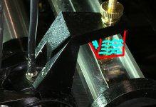
kindly see attached picture. I used the wrong word (enclosure) a tiny chamber filled with damping fluid. Will that work ? or one can use tuned mass damping like Dual tonearm.
Super and AVWerk,
kindly see attached picture. I used the wrong word (enclosure) a tiny chamber filled with damping fluid. Will that work ? or one can use tuned mass damping like Dual tonearm.
Attachments
Hi Jim,
I would recommend a redesign of the paddle. As has been mentioned in previous posts the current paddle offers high damping in the lateral plane but little in the vertical.
The main source of infrasonic lateral modulation is record eccentricity and this occurs, for 33.3rpm , at 0.55hz. This is way below the lateral resonant frequency of your arm.
The main source of infrasonic vertical modulation is record warps. As you pointed out, your vertical resonant frequency is within the range where warps occur with significant amplitude. Even though you have significant record clamping you will still have a greater resonances occurring in the vertical plane than the lateral. Therefore you require greater vertical damping than lateral. (with my arm the vertical damping, due to friction, is three times the lateral) A differently shaped paddle can achieve this. Determining the best shape will probably required a bit of experimentation. With a correctly shaped paddle I think that a lower viscosity fluid would work better than the 3500cst you currently use. Forgive me if your actual viscosity is different, I quote from memory. Again the ideal would require further experimentation.
I like the idea of magnetic damping as it is IMO better than silicon fluid at very low levels of damping. It is more difficult to set vertical damping to be greater than lateral so may not work as well in application.
Niffy
Since you cannot dampen an actual record warp, all you can do is ride over it and not excite the arm or show any resistance to its behavior.
Adding more vertical dampening resistance at similiar frequencys (arm and warp) will deflect the diamond since you have 1 control and not the other.
The vertical knife design seems appropriate in this case, but it is relatively easy to change paddle designs to test it out..,. Maybe my thinking is off on this
Even though a rim clamp is miles ahead of anybody making TT,s these days, a vacuum platter removes all warps that perimeter weight can,t quite accomplish. Certainly better than nothing.
The ratio of vertical to lateral dampening becomes easier to adjust when you know the record is perfectly flat.
I,ll bet if you add vertical dampening the resonant hump will shift rather than attenuate at similiar resonant frequencys
I could be wrong on this speculation
Regards
David
Hi Hiten,
It works ONLY IF you have a mechanism to move the container along with cartridge.
I don’t know Dual tonearm so I can’t comment on it.
Jim
It works ONLY IF you have a mechanism to move the container along with cartridge.
I don’t know Dual tonearm so I can’t comment on it.
Jim
Hi Niffy,
I am thinking of making a pyramid shape paddle and may use plastic as material because plastic has high buoyancy force so it will add more damping force. But I am not sure for now because if it is plastic and it floats on or submerges in silicone fluid, it will produce a small up lift force. It may not be needed.
The silicone fluid I am using now is about 3500 CST. I can’t tell exact CST since it is a mixture of 3000 and 5000. I may use low CST once I modify the paddle. I think Walker Audio uses 30 CST which is like motor oil. I am thinking something like 1000 CST. High CST gives me wider range to adjust the damping.
Hi David,
Vacuum platter is nice but it involved a bit too much for diyer like me. Also, not all vacuum platter sounds same. Some of vacuum platter may reduce warps but in the meantimes, it may change the sound due to the material used for vacuum mechanism.
I don’t know if vertical damping will attenuate or shift resonance frequency. I will do some experiments to see what happens.
Jim
- Home
- Source & Line
- Analogue Source
- DIY Air Bearing Linear Arm