
Quote: Simple question – to run the ACA mini in parallel mono, do I parallel both the positive and negative outputs and run a Y cable into the inputs?
YES
Now, to make it even simplier, if my memory serves me well - seems I did it ages ago - the inputs grounds are already in parallel (though you might not bother if using Y cables) and the output/LS grounds are already in parallel so that saves you 50% of the work on that side. Note that paralleling them didn't change anything and didn't at mine introduce any ground loops, but well, it is not needed as already there at grounds so we did without.
I hope this helps
Claude
Ah, a useful picture has been posted exactly same time I posted my long text,- I probably should have waited for a few minutes LOL!
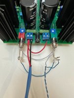
That's what I did, but if I remember well the ground connection at the RCA inputs is not needed as already there on the Mini - just check please to make sure. On 6L6's excellent picture that would be the blue bottom "smiley" cable LOL
All other cables in the pix are mandatory needed
That's what I did, but if I remember well the ground connection at the RCA inputs is not needed as already there on the Mini - just check please to make sure. On 6L6's excellent picture that would be the blue bottom "smiley" cable LOL
All other cables in the pix are mandatory needed
Thank you, Stanislav and ClaudeG.
I knew it was in there, but the search function didn’t turn it up. And 3000+ posts is a lot to scroll through!
Also, the reply from 6sX7 above, directing me to the ACA mini directions, was different/ that one connected the black (negative) outputs, whereas the 6L6 photo connects the red (positive) outputs. As ClaudeG says, if the negatives are already connected, it won’t matter.
Thank you again- I’ll keep looking for the post from 6L6 thst came with the photo!
Last edited:
^ As you sort this all out... it's critical to note that the "signal" or "out" for the original ACA is connected to the 'black' binding posts sometimes noted as '-' for a typical build. The red binding posts sometimes noted as '+' are connected to audio GND.
The ACA Mini has the "signal" or "out" connected to the 'red' or '+' in a typical build.
DO NOT follow the instructions for the original ACA per 6sX7. That is not directly applicable to the Mini.
DO follow the pic posted above from Stanislav. Note that ClaudeG has advised correctly that it's not necessary to have the GND tabs on the RCA inputs shorted with a jumper wire b/c they are connected via traces on the PCB. (See the article and/or beep it out / look at the traces on your board). However, if you intend to use a simple commercial "Y-cable" with the GND internally connected, it won't hurt a thing.
Last edited:
Thank you for the explicit confirmation, ItsAlInMyHead. And for the +/- reminder about the outputs.
I’m ready to do it now!
I’m ready to do it now!
^ Any time.
Also - For reference. Links below should take you to Posts 1833 and 1840
Also - For reference. Links below should take you to Posts 1833 and 1840
You could also run the channels in parallel, use a Y-cord to the input, and parallel the output jacks. I had one wired that way just a couple of days ago and totally forgot to get any photos…. Whoops.
Anyway, it worked great.
Anyway, it worked great.
- Home
- Amplifiers
- Pass Labs
- DIY ACA mini