When I powered it up with all (2k but not Bournes) pots turned counterclockwise I could smell heat and then smoke.
Do the pots installed have a different arrangement of CW and CCW than the Bournes unit?
I don't know about easier...but there's this video:Are there easier instructions than in the Pass Article?

I wonder if the pots you used have the same pinout as the Bourns....all (2k but not Bournes) pots turned counterclockwise I could smell heat and then smoke...
Funny story - My son Perry (camera man) and I did a few dry runs before making the video above. I'm watching the meters which are attached to LEFT channel while mistakenly turning the pots on the RIGHT channel until Perry yells "Hey Dad...It's starting to smoke!". Apparently the "Magic Smoke" is only trapped in the active devices and you can let a little smoke out of the resistors and still be okay because the amp still worked fine.I could smell heat and then smoke.
That's two meters, cheating!!!I don't know about easier...but there's this video:
Biasing this with one meter is like trying to solve the rubik's cube, blindfolded, underwater, and drunk!!
That said I think i got it!
I can't believe this sounds this good!!
I'm going to do some comparisons with my modded ACA !!!
Sounds so good driving my Klipsch Forte's
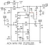
If you compare the pcb to the schematic, P1 and P2 should have their wiper shorted to one side of the pot, but the official board does not have those shorted connections. (Sorry Papa!)
Nelson's explanation: ACA Mini pot wiper
Thanks to all for the feedback. Given that I only received the board from the store a week or so back I had assumed it would have been the latest version with the corrected traces. Maybe not. Will resume the battle with the pots in an hour or so, and can I further assume that if I achieve the correct stable settings that all is well with nothing more to do?
With the the 12inch fullrange speakers it’s even better. A lot of rasorsharp details, good bass and very dynamic musicality. A little less attack compared to the ACA but perfect for comfortable listening with jumpers in. For critical listening will take the jumpers out.Btw
The sound is excellent with the oval fullrange spakers. I‘m very happy and many more thanks to the creator of this wonderful amp!!!
In post #1972 Chris Jones mentioned his preferred bias settings, thank you!
Just built this kit and my VB in both channels is 0 no matter if I turn the pots. My VO is 11.94 when pots are all the way counterclockwise and only goes up from there when I turn the pots. Any suggestions? Thanks.
Given that the midpoint is correct (VO) I would guess the small signal FET's are not passing sufficient current to develop enough gate voltage to turn the power FET's on.
What is the highest voltage you can you measure across each preset as you turn them? You need around 4.5 volts or so to begin to turn the FET's on. Measuring between gate and source (the two outer pins) of the power FET's is the same points but just be careful not to short the pins if you do that.
(was there a change in value to 2k for those presets somewhere down the line to accommodate this kind of thing or am I imagining that?)
could the problem be that I put both Q4s and one Q3 in backwards and when I screwed then to the heat sink it broke them? One Q3 reading is 3.45.
I’m getting no change in VB as I turn the pots.
We know 🙂
Measure the gate/source voltage on each power FET and tell us what the highest voltage you can achieve on each FET by adjusting the presets. It should alter between zero and some value. What is that value?
Q4 near ground pin and preset P2: 0 to -15.4; P1: 0 to 0
Q3 near red input And preset P2: 0 to 2.6 slowly rising more; P1: 30 to 3 then still slowly rising
Q3 near green input and preset P2: 0 to 0; P1: 0 to -9.4
Q4 near LED and preset P2: 0 to -9.75; P1: O to 0
Q3 near red input And preset P2: 0 to 2.6 slowly rising more; P1: 30 to 3 then still slowly rising
Q3 near green input and preset P2: 0 to 0; P1: 0 to -9.4
Q4 near LED and preset P2: 0 to -9.75; P1: O to 0
It looks like the JFETS on one side are backwards, as are the MOSFETS.
- Home
- Amplifiers
- Pass Labs
- DIY ACA mini