Hi there, I started building my kit today and discovered some anomalies with the small resistors.
The photo below shows the start of the build and the small resistors that arrived. The one 6.8K I received is installed at R0.
Question: Have there been mods made and the values shipped are correct?
Thanks for any advice or help.
It is a wonderful kit and I'm excited to build it!
Al in New York

- Instead of getting 3 x 6.8K resistors for R0 and R4, I got 1 x 6.8 and 2 x 22K.
- Instead of 4 x 221K for R2-R3, I got 2 x 221K and 2 x 200K.
The photo below shows the start of the build and the small resistors that arrived. The one 6.8K I received is installed at R0.
Question: Have there been mods made and the values shipped are correct?
Thanks for any advice or help.
It is a wonderful kit and I'm excited to build it!
Al in New York
Yes, what you have is correct.
The BOM was updated as of 10/22 per NP:
R2=200K qty 2
R4=22.1K qty 2
RO and R3 remain the same
The BOM was updated as of 10/22 per NP:
R2=200K qty 2
R4=22.1K qty 2
RO and R3 remain the same

Seems to be in post #1355: https://www.diyaudio.com/community/threads/diy-aca-mini.379037/page-68#post-7156140
Thanks Dennis. You beat me to it, being Sunday morning and all!
The most recent kit includes the original value of 15K for C2, C3 and 3.3F for C6.
The most recent kit includes the original value of 15K for C2, C3 and 3.3F for C6.
Last edited:
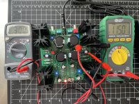
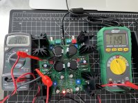
Hello again! I finished the build and am now starting the bias operation and have a question about the initial readings.
My meter shows nearly 12 volts from VO, with trimpots both at max counter-clockwise rotation. The voltage of VB is 0.
In the Nelson Pass article, it says both initial voltages should be close to 0. "Initially the values will be at or close to 0 volts."
My meter leads are connected this way:
VO - Black to ground lug at right of power switch; Red to VO lug near supercapacitor. I soldered wires to the lugs to connect the meter leads to.
VB - Black and red to either side of R8.
Photo attached.
I get the same reading on both channels of the amp. The only complication in the build was I installed Q1 the wrong way around on the left side of the amp (looking at it from the power switch end) and had to de-solder and re-solder it. I held a bit of ice in tin foil against the transistor to keep it cool during that operation. And in any case, the 12 volt readings are on both sides.
Any advice would be greatly appreciated.
Thanks in advance.
Al in NY
Attachments

Any advice would be greatly appreciated.
Thanks. Got it biased and it works.
But it sounds scratchy. The distortion is mostly audible in the high and mid-high frequencies.
Wondering what the brain trust here would suggest for a starting point for troubleshooting.
I tried two different sources to see if that was the problem: One was the headphone output of my Mac; the other was the RCA outputs of a Topping D10s DAC. Distortion was the same. I'm playing music from spotify.
It's OK when the volume is set to halfway or less, and the overall output is rather low. But over halfway mark the distortion increases. I tried two sets of speakers. Yamaha AW1s (outdoor knockaround speakers) and Buchardt S300s.
Attachments
Last edited:
@ALNY
The color banding on the 22.1K resistor in position R4 looks odd to me. Shouldn't a 22.1K 1% resistor banding be red/red/brown/red/brown? Did you check each resistor against the schematic with your meter to insure proper value while installing?
With another look it seems like you might have a four band red/red/orange/green which would be a 22K .5%
Last edited:
Thanks Kevin. I checked the R4s again and they show about 21K. I am measuring all of the resistors again and comparing with the specifications. Some are showing that they're off by quite a bit. For example:
R2 is 109K instead of 200K. That's 109, not 190.
R3 is 119K instead of 221K.
I'll attach the full list when when I finish measuring.
R2 is 109K instead of 200K. That's 109, not 190.
R3 is 119K instead of 221K.
I'll attach the full list when when I finish measuring.
If the resistors were measured in the circuit, the readings may not reflect the true values as there may be other components that are in parallel with the them.
I looked up the specifications for the Yamaha AW1 and it is 6 Ohm nominal impedance with sensitivity of 86db/W/m. The Buchardt S300 is 4 Ohm nominal impedance with sensitivity of 88dB. The ACA Mini puts out about 6W into 8 Ohm and about 8 to 9W into 4 Ohm. Both speakers are not very sensitive and the ACA Mini does not output much power, so perhaps that is why the undistorted volume was not very loud.
I looked up the specifications for the Yamaha AW1 and it is 6 Ohm nominal impedance with sensitivity of 86db/W/m. The Buchardt S300 is 4 Ohm nominal impedance with sensitivity of 88dB. The ACA Mini puts out about 6W into 8 Ohm and about 8 to 9W into 4 Ohm. Both speakers are not very sensitive and the ACA Mini does not output much power, so perhaps that is why the undistorted volume was not very loud.
Thanks for the great feedback. On reflection, it's likely I built it correctly because I checked each resistor before installing. And as Ben pointed out, the in-circuit measurements don't mean much. Plus, it does actually work.
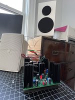
So... I just put both outputs into one of the Yamaha AW1 speakers and it sounds acceptable at moderate volume. Same with a single Buchardt. There's a lot of richness in the tone. Definitely not a blaster of an amp. I'm listening to Muddy Waters' "Folk Singer", T-Bone Walker's "Super Black Blues" and Howard Roberts' "Dirty Guitar Player" and the grit sounds ... kinda good? It's definitely there! Bill Evans Trio sounds not so hot, since the grit really doesn't go well with his piano. 🙂
What might be going on is that my ears are so used to the sound of non-class-A solid-state amps, like my Hafler DH-200 and Harman Kardon 330C. I recapped both and put upgraded circuitry designed by Fantasia Audio (on Ebay) in the Hafler. Those are really clean sounding and much more powerful of course. This little Pass amp is a different animal, and that's part of what prompted me to build it. Curious to know thoughts on how this design compares with tube class A in terms of sound character?
If there are ways to clean up the grit even a little, please share thoughts. The heat sinks are totally cool, so is there room to increase VO a little to boost the output? I'm running at VO=11.65 volts and VB=300mV now. Upper limit?
It may be that Ben's comment about more sensitive speakers is the most effective way to appreciably clean up the sound.
What are your thoughts on good speaker pairings and a good target for sensitivity level. Something over 90dB at 1 watt/1 meter?
Attachments
Hi
I’d odd that your heatsinks are totally cool. Mine are at about 55C, not cool at all. Please check your bias value, you can increase it up to 350mV.
For speakers I’d say aim for 94-96 dB to be able to really enjoy this fine amp.
Eric

I’d odd that your heatsinks are totally cool. Mine are at about 55C, not cool at all. Please check your bias value, you can increase it up to 350mV.
For speakers I’d say aim for 94-96 dB to be able to really enjoy this fine amp.
Eric
My heatsinks will be 50-55 C at 300 Vb and 11.60 V0. Your LED light doesn't pulse, does it?
If your SMPS was stuck trying to fill your capacitors and pulsing, the gritty sound would be there and the heatsinks would remain cold. I don't think it would bias to your levels, though.
If your SMPS was stuck trying to fill your capacitors and pulsing, the gritty sound would be there and the heatsinks would remain cold. I don't think it would bias to your levels, though.
The LED is not pulsing. When I disconnect the power supply from the jack on the board, it takes about 40 seconds for the sound to fade out. The LED remains lit even after that. The sound quality begins to degrade about 2 seconds after the supply is disconnected.
- Home
- Amplifiers
- Pass Labs
- DIY ACA mini