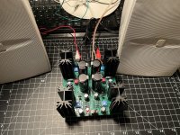
Darn. I am not sure why your heatsinks are cold and the sound has a grit. Neither sound right. What is the green gator clip attached to in this picture? Why not directly hookup your speaker wires?

I have had a hard look at resistors R8 and R9. They should be 0.75 Ohm but they might be 75 Ohm based on the colours that I see. If that is the case, that would explain the cold mosfets. Please check their resistance. Unsolder and lift one resistor leg if necessary to get an accurate measurement.

All of the 3W resistors' colour bands relative to their values are weird. If the fifth band is ignored, the values would be correct. But the resistors have five bands.
OK, I checked with Vincent and it's a tempest in a teapot. The correct resistors were shipped
and the values measured in and out of circuit reflect either the meter accuracy or that they
were measured in circuit. The odd bands are simply from a different source and 2% tolerance,
reflecting cost and supply issues. They will work fine.

and the values measured in and out of circuit reflect either the meter accuracy or that they
were measured in circuit. The odd bands are simply from a different source and 2% tolerance,
reflecting cost and supply issues. They will work fine.
My assumption for the 3W resistors:
The separation is between the 3rd and 4th band.
The 4th band is the tolerance and the 5th band is then the temperature coefficient.
I know this definition, however, only for 6 bands.


The separation is between the 3rd and 4th band.
The 4th band is the tolerance and the 5th band is then the temperature coefficient.
I know this definition, however, only for 6 bands.
Last edited:
With the specification of the temperature coefficient, the value of 0R75 and 0R33 can only be described with three bands, because there is no color for a factor of 0.001.
When using four bands and with a factor of 0.01, the first band should be black, which is not allowed or intended.
When using four bands and with a factor of 0.01, the first band should be black, which is not allowed or intended.
Last edited:
But still, either one of those speakers should play to a reasonably loud level with no distortion using a fraction of a watt.I looked up the specifications for the Yamaha AW1 and it is 6 Ohm nominal impedance with sensitivity of 86db/W/m. The Buchardt S300 is 4 Ohm nominal impedance with sensitivity of 88dB. The ACA Mini puts out about 6W into 8 Ohm and about 8 to 9W into 4 Ohm. Both speakers are not very sensitive and the ACA Mini does not output much power, so perhaps that is why the undistorted volume was not very loud.
It’s the fact that his sinks aren’t warming up at all that is troubling to me.
@ALNY
Are we sure it’s biased at 300mV and not something like 30mV? I know, I’m reaching for straws here…but we need to determine why the MOSFET’s aren’t getting enough voltage.
Last edited:
To my initial surprise, I have SR1's that are a tougher load, and as long
as I'm not having a disco party, ACA mini seems to work fine...
That said, we want a bias somewhere between 400 and 500 mA, which
is 0.3+ Volts DC across the .75 ohm resistors.
😎
as I'm not having a disco party, ACA mini seems to work fine...
That said, we want a bias somewhere between 400 and 500 mA, which
is 0.3+ Volts DC across the .75 ohm resistors.
😎
Thanks @Nelson Pass and everyone. Wow, what an amazing forum, and project.
I'm ashamed to say that I had screwed up the biasing, but it took me awhile to get there. In between work emails, I pulled out R9 and tested it. 0.75 ohms. So I turned the pots back to full counter-clockwise and started over with biasing. At this point I began looking seriously at my three multimeters. After work I got new batteries and then realized two of them are just junk. So I biased it with the one good one, switching back and forth between VB and VO, and estimated I had been low on VB by a factor of 10.
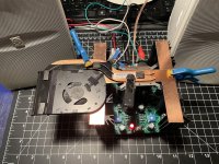
Now the heatsinks are toasty and the sound is wonderful. It's driving the Yamaha speakers very well. Buchardts tomorrow.
I even tried on my prototype "cooling hat" - made from a salvaged Macbook fan and some copper strips. Not sure about it yet..
I really appreciate all of your help. Thank you.
Anyone recommend a reliable meter for around $100?
I'm ashamed to say that I had screwed up the biasing, but it took me awhile to get there. In between work emails, I pulled out R9 and tested it. 0.75 ohms. So I turned the pots back to full counter-clockwise and started over with biasing. At this point I began looking seriously at my three multimeters. After work I got new batteries and then realized two of them are just junk. So I biased it with the one good one, switching back and forth between VB and VO, and estimated I had been low on VB by a factor of 10.
Now the heatsinks are toasty and the sound is wonderful. It's driving the Yamaha speakers very well. Buchardts tomorrow.
I even tried on my prototype "cooling hat" - made from a salvaged Macbook fan and some copper strips. Not sure about it yet..
I really appreciate all of your help. Thank you.
Anyone recommend a reliable meter for around $100?
Attachments
Never imagined you as the disco type, but whatever……as long as I'm not having a disco party, ACA mini seems to work fine...
Solving the problem is the greatest satisfaction in DIY.

Hi together,
parts yesterday deviled for all three pcbs but two question because I ordered the parts from Nelsons PDF. From the hint here that exists a newer revision of the BOM.
1. R4 was 6k8 and now 22k1 so I think 22k would also ok (what is 1%)?
2. For P1 / P2 was 1k .... I saw the hint of FET bag to late (wrote 1k5 to 2k for the pots on it) but I will try it, changing later will be easy done or can I make some parts defective - I think not only I can not reach the needed voltages.
@ALNY:
I picked up a UNI-T UT61 meter 7 or 8 years ago. It was pretty inexpensive and has served me well. I'm surprised your two meters threw you off so much. Do they behave better with fresh batteries?
And congratulations on solving bias problem.
I picked up a UNI-T UT61 meter 7 or 8 years ago. It was pretty inexpensive and has served me well. I'm surprised your two meters threw you off so much. Do they behave better with fresh batteries?
And congratulations on solving bias problem.
1. was 6k8 and now 22k1 so I think 22k would also ok (what is 1%)?
Any tolerance is fine for those.
1.5k is great but harder to get, so I just see to it that input jfets have idss high enough to work with 1k.2. For P1 / P2 was 1k .... I saw the hint of FET bag to late (wrote 1k5 to 2k for the pots on it) but I will try it, changing later will be easy done or can I make some parts defective - I think not only I can not reach the needed voltages.
There is a link to the most recent BOM in post #1,355 and also on the diyaudiostore.com page for the ACA Mini....From the hint here that exists a newer revision of the BOM.
Regarding recent concerns regarding out of spec readings of power resistors, I discovered a link in step 6 of the ACA Mini build guide, which I overlooked while building 2 of my own, that discusses the difficulty in accurately measuring low resistance resistors.
Power resistors: It's difficult to measure these because the resistance of your multimeter leads (normally 0.2-0.4Ω) will be added. You can measure your leads and subtract the value, just trust the values which are printed on them, or build a low resistance value test rig.
There you have it. DIY is a great opportunity to learn something new every day!- Home
- Amplifiers
- Pass Labs
- DIY ACA mini