@Nelson Pass on the Right V0 11.79 to 11v..81 (I managed to improve by replacing R9 which was burnt) VB 0 to 4 MV.
Left channel Vo at 11.11 to 12.90 and VB 0 to 126 MV .
Left channel Vo at 11.11 to 12.90 and VB 0 to 126 MV .
@Chilaquiles
Are you confident you are following the bias procedure correctly?
Did you happen to watch this video?
ACA MINI BIAS PROCEDURE VIDEO
Are you confident you are following the bias procedure correctly?
Did you happen to watch this video?
ACA MINI BIAS PROCEDURE VIDEO

From my understanding, a high value C2 (output coupling cap) will act inductively . Do I need to parallel high Q smaller caps to improve low frequency response? Comments appreciated for the output coupling cap.
@Chilaquiles
With all pots turned completely counterclockwise, what reading do you get at VO when you initially turn the amp on (giving it a minute or so to stabilize)? Report measurements for both channels please.
With all pots turned completely counterclockwise, what reading do you get at VO when you initially turn the amp on (giving it a minute or so to stabilize)? Report measurements for both channels please.
The capacitive value IS high to achieve good low frequency response! No need to improve something 😊From my understanding, a high value C2 (output coupling cap) will act inductively . Do I need to parallel high Q smaller caps to improve low frequency response? Comments appreciated for the output coupling cap.
Last edited:
Simple answer would be no. The effects of ESL (equivalent self inductance) and ESR (equivalent self resistance) on a large cap like this really are negligible over the audio band and way beyond. It is in the higher frequencies inductance would come into play, but it is a non issue here.From my understanding, a high value C2 (output coupling cap) will act inductively . Do I need to parallel high Q smaller caps to improve low frequency response? Comments appreciated for the output coupling cap.
Edit... ESL and ESR. 'self' (why did I type that?) should be series of course.
As @Franz Gysi says, the high capacitance value is to maintain LF response.
Last edited:
Thank you Mooly n Franz. Looks like I have to look into higher sensitivity speakers and/or DIY full range speakers for the amp as an improvement. Need $ tho.
@Chilaquiles
With all pots turned completely counterclockwise, what reading do you get at VO when you initially turn the amp on (giving it a minute or so to stabilize)? Report measurements for both channels please. with all pots counterclockwise I have Vo left at 00 mv. Vo right at .01mv. @KevinHeem
@Chilaquiles
Just to recap:
Post #2077 - Left channel adjusted "fine" at VO = 11.5 and VB = .30V. Right channel VO = 11.85 VB = "VB is fine" (I'm not sure what that means).
Post #2082 - Left channel VO in the range of 11.11 to 12.90 and VB 0 to 126 mV. Right channel VO = ~11.80V and VB= 4mV. Also mention of a burnt resistor R9.
Post #2090 - Pots all counterclockwise VO Left 0, VO Right .01 (There should be voltage at VO)
This isn't making much sense...is there any information you can add that would fill in the blanks? Are you being consistent in the way you are measuring VO and VB? If you over-turn those trim pots there will be smoke (I know this from experience).
@KevinHeem apologies not trying to be frustrating. I took new readings with pics.
All pots all the way counterclockwise I have:
Left VB 00.00 & Vo 11.89
Right Vb 01.8mv & Right Vo 11.83
All pots clockwise I have
Left VB 91.60mv & Vo 11.79
Right Vb 1.0mv & Right Vo 11.86
No smoke on either. Pics below.


All pots all the way counterclockwise I have:
Left VB 00.00 & Vo 11.89
Right Vb 01.8mv & Right Vo 11.83
All pots clockwise I have
Left VB 91.60mv & Vo 11.79
Right Vb 1.0mv & Right Vo 11.86
No smoke on either. Pics below.
Okay, those are good numbers! Now if you start to turn P2, can you pull VO down under 11.5 V and get a few mV on VB?
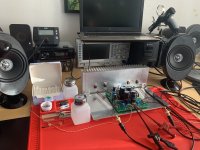
Testing at stock bias. Sounds actually spookily fricken toetappingly beautiful with the linear lab PSU. @24V.
Yeah, only the small, beautifully smooth, but almost bassless, build bench KEF aluminium enclosure point source speakers.
I am now MORE than curious how this will sound on the really big rig.
🎷🙂🎸
Yeah, only the small, beautifully smooth, but almost bassless, build bench KEF aluminium enclosure point source speakers.
I am now MORE than curious how this will sound on the really big rig.
🎷🙂🎸
Attachments
you can fix the pcb direct on heatsink to have short mosfet wire.....Testing at stock bias
Yeah, thats probably not a bad, but a fairly good idea. Less is more. Clean is Clean. So, since i am reuseing the heatsinks from my old Yamaha and my not so old Onkyo home cinema recievers, on my first and my second mini, thats exactly what i am gonna do. So here is teh planned setup for the no 2.
Comin up, one of these days: Pass ACA Mini no 2 🙂❤️

Comin up, one of these days: Pass ACA Mini no 2 🙂❤️
Hi all,
I have tried the search but found no suitable result so I just ask you.
Can I power up the amp also with only 20V and should be something changed (have three 20V power supplies lying here)?

I have tried the search but found no suitable result so I just ask you.
Can I power up the amp also with only 20V and should be something changed (have three 20V power supplies lying here)?
Yes, and you can consider biasing the output devices about 20% higher when you do.
Hi Nelson,
may thanks for this info .. will stay first at the noticed values from your PDF ... later then more. ;-)
may thanks for this info .. will stay first at the noticed values from your PDF ... later then more. ;-)
- Home
- Amplifiers
- Pass Labs
- DIY ACA mini