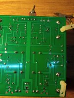
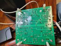
It appears that the ACA mini PCB that I received from the store is missing the trace between pin2 & 3 on all the trimpots.
Verified visually and also with the continuity function on my DMM.
As such the trimpots are voltage dividers and not rheostats.
Also that way the drains of Q1 & 2 are connected only to pin3 (CW) of the trimpots. Connection to the gates of Q3 & 4 is only through pin2, the center pin of the trimpot.
Don't think that's how it is on the original circuit diagram. The PCB artwork in the original file also shows a clear connection between pin2 & 3.
I fitted small jumpers underneath and now it is according to the schematics.
Wondering if that's a faulty batch of boards or a deliberate feature.
If it's the latter I haven't read anything about it so am not aware of any changes from the original.
Would like to hear what the other builders think or know about this.
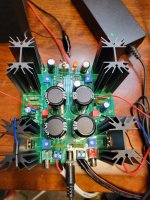
Some photos below.
Verified visually and also with the continuity function on my DMM.
As such the trimpots are voltage dividers and not rheostats.
Also that way the drains of Q1 & 2 are connected only to pin3 (CW) of the trimpots. Connection to the gates of Q3 & 4 is only through pin2, the center pin of the trimpot.
Don't think that's how it is on the original circuit diagram. The PCB artwork in the original file also shows a clear connection between pin2 & 3.
I fitted small jumpers underneath and now it is according to the schematics.
Wondering if that's a faulty batch of boards or a deliberate feature.
If it's the latter I haven't read anything about it so am not aware of any changes from the original.
Would like to hear what the other builders think or know about this.
Some photos below.
Attachments
Mine is the same way. Interesting catch. But it does seem to work as is.
So is the published schematic in error or the board layout?
So is the published schematic in error or the board layout?
Last edited:
What?? Yea well, do we have some good old circuit explaining and analyzing dude who could shed some light on this?
Im still building enclosures and havent yet completed the twin mini amps. But before to late and Sooon enough there Will be some:
🎷😎🎸
Im still building enclosures and havent yet completed the twin mini amps. But before to late and Sooon enough there Will be some:
🎷😎🎸


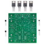
Well, that's the whole point, there's a big difference what's in the article and what's on the actual board that I have.The top side copper has the trimmer connection - see the board graphics in Nelson's pdf article.
Check also the photo from the store.
Attachments
Pa likely opted to have fixed resistor value in JFet drains
not likely a mistake, he just didn't informed us of later change
besides, he likes leaving puzzle here and there
not likely a mistake, he just didn't informed us of later change
besides, he likes leaving puzzle here and there
I agree. It's not likely a mistake on the board. There are a couple of hundred kits out there singing happily! 
So, we are now back to not good illumination and no true clarity given to the fine soldiers on the really beautiful, musically globally truely mighty, and fairly best sort of vintage, First Watt, greenhorn pirate ATTACK ship?
🎷😎🎸
🎷😎🎸
It goes In the movie Something like: ”…I have seen ATTACK ships on fire, off the shoulders of the Orion…”
🙂
🙂
What? No more music from JD???
Just joking 🙂
So. Here it is. We are talking class pure A from Sweden. Best played on pure class A. HEAT. BASS. SUMMER. Happy Music. The singer Agneta Fältskog fom ABBA.
THE HEAT IS ON
The same cool bass playing dude as from the original ABBA group…
Make sure to crankit. Never ever harch. Harch = Burn it, do not sell it 🙂🤚❤️
On the lack of a connection between the trimmer legs on the pcb, that was a known thing with the original PCB (please see post #454):
https://www.diyaudio.com/community/threads/diy-aca-mini.379037/page-23#post-6898376
Perhaps the currently available PCBs are still based on the original art work?
https://www.diyaudio.com/community/threads/diy-aca-mini.379037/page-23#post-6898376
Perhaps the currently available PCBs are still based on the original art work?
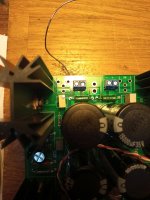
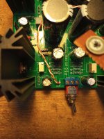
Hiya. I have been adjusting my amp for a bit. Left channel is fine, Vo at 11.5 and Vb at .30. The right (llright on top view, left on the bottom) channel however I cannot get Vo below 11.85 no matter how I tune both pots. Vb is fine. Any ideas? I searched the posts but what I saw were not clear (well my understanding) on this issue. Maybe an issue with mossets? Posted pics just in case.
Attachments
First disconnect the speaker wires, you don't need them to adjust bias and Vo.
Second, see if that channel gets power, 24v.
See the schematic for suitable test points.
Once satisfied there's power check for bad solder joints around P1 &P2 and all around.
If no luck come back here, someone will lead you further.
Good luck
Second, see if that channel gets power, 24v.
See the schematic for suitable test points.
Once satisfied there's power check for bad solder joints around P1 &P2 and all around.
If no luck come back here, someone will lead you further.
Good luck
- Home
- Amplifiers
- Pass Labs
- DIY ACA mini