The two adjacent pads near the VB label.
VB is bias voltage, measured across R8. Papa made the pads to make it easier during adjustment.
VB is bias voltage, measured across R8. Papa made the pads to make it easier during adjustment.
Last edited:
Ok, thanks a lot… Stupid of me… 😀 I now have ~11.5 on Vo and - 115mv on Vb. I’m using the red probe on my meter to the nearest pad to Vb. The heat sinks are warming up. Why might my measured Vb be negative?
I’m now up to 11.5v on Vo and ~-300mv on Vb. I saw in NP’s notes not to worry if Vb is negative. I took this to mean initially. Is it ok as a final bias figure? Forgive my ignorance, please.
I have to say that this is a wonderfully helpful community with a high tolerance of individual incompetence which I have really come to appreciate…
Thankyou all…
I have to say that this is a wonderfully helpful community with a high tolerance of individual incompetence which I have really come to appreciate…
Thankyou all…
Don't worry about the negative measure. Just swap the probes if you are more at ease with a positive reading. You are indirectly measuring a current by checking the voltage across R8: only the absolute value does matter. The direction of the current is imposed by the circuit. Remember to check again after a while, because the current will drift slowly up until the temperature is stable.
It’s perfect, if it’s stable at these values after 1h don’t touch anything, you’re all set.I’m now up to 11.5v on Vo and ~-300mv on Vb. I saw in NP’s notes not to worry if Vb is negative. I took this to mean initially. Is it ok as a final bias figure? Forgive my ignorance, please.
I have to say that this is a wonderfully helpful community with a high tolerance of individual incompetence which I have really come to appreciate…
Thankyou all…
Time to go enjoy some music
Eric
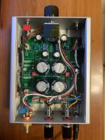
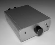
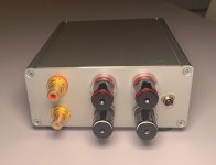
This is my ACA mini essentials kit assembled inside a small 160x125x51.5mm (6x5x2 inches) Hammond 1455Q1601 enclosoure, RS part number 773-3003.
This handy size is a popular one for small class D and dacs from China. I selected this Hammond extruded alluminium enclosoure because it does have channels to slide in PCBs and it happens to be almost the perfect size for the ACA mini board.
To fit the board inside this chassis I had to make a few small modifications:
To build the amplifier I shaved off with a metal file half a millimeter of PCB matherial from the left and right side of the PCB, to made it fit into the bottom channel of the Hammond 1455Q1601 chassis. To avoid shorting with the chassis, I wrapped 2 layers of narrow mylar tape on the left and right PCB sides.
I drilled 4 holes with a 3mm drill bit on the bottom of the chassis, using the PCB as a dime, to host 3x30mm screws with dual function: they hold the bottom feets in place and the protuding part of the screw is holding the PCB, so it cannot slide back and forth in the channel. Feets height is 10mm and they are metallic, to keep the chassis at a distance from the table enabling air circulation on the bottom. They must be metallic to avoid distortion due to the high chassis temperature.
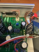
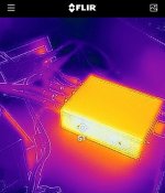
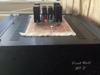
The power mosfets are mounted directly on the sides of the chassis, with insulating pad and washer. My original plan was to bend and extend the legs and solder them on the PCB from the top. This is fast and easy but makes servicing cumbersome. I used the arrangement on the picture instead. It makes further works very easy and thermal coupling is better. The channels on the chassis are not a ideal surface, but it is good enough according to the Flir thermal camera measurements. It is important to check the insulation betweek the mosfet tab and the chassis, because if the mounting screw is too tight, the insulating pad may be damaged by the sharp edges of the channels.
I've found that the initial VB ajdustement must be lower than the specified 150mV because the chassis temperature will increase by 30-35C over the ambient temperature, more than the original specification due to smaller heatsink surface. I set VB at 300mV at thermal steady state with the lid closed, this had to be done iteratively over several hours. 300mV is 10% less than the suggested optimal value because I used 0.82 ohm for R8 and R9 instead of 0.75 ohms and Vb is measured across R8. Vb decreases to 240mV with the lid open due to the lower temperature inside the enclosoure. My original plan was to bolt a supplemental heatsink on both sides using the same screws that are holding the mosfets, this would cool down things considerably and bring back the dissipation rating at specs enabling the full performance. I was unable to hear any difference on my setup by briefly increasing the current, so I scrapped the plan and I kept the enclousoure as is, smaller and lighter. The only downside is that 50C does exceeds the IEC 60065 max allowed rating of 40C. With additional heatsinking, the black 1455Q1601BK would probably be a better choice.
This handy size is a popular one for small class D and dacs from China. I selected this Hammond extruded alluminium enclosoure because it does have channels to slide in PCBs and it happens to be almost the perfect size for the ACA mini board.
To fit the board inside this chassis I had to make a few small modifications:
- C2 and C3 height must be 35mm. I selected Nichicon LGU1E103MELA (RS part number 846-6916). They are 10000uf 25v instead of 15000uF, but they seems to work just fine on this application. The 105C temperature rating is important, because the chassis becomes hot inside.
- P1 and P2 are multi-turns Bourns PV37W102C01B00 (RS part number 769-2227). They made the adjustements much easier. The pinout of this 1k trimmer is the reverse of the original single turn trimmer, so the adjustement must start with the trimmer turned fully clockwise.
- R8 and R9: I was unable to source 0.75 ohms resistors, so I installed 0.82 ohms resistors with same power rating (10% increase over design value).
- I added a RK27 50K potentiometer and 3.3uF Vishay capacitor at the input, to use this amplifier with a high-output DAC I have.
- I used a Mean Well GST90A24-P1M power supply
To build the amplifier I shaved off with a metal file half a millimeter of PCB matherial from the left and right side of the PCB, to made it fit into the bottom channel of the Hammond 1455Q1601 chassis. To avoid shorting with the chassis, I wrapped 2 layers of narrow mylar tape on the left and right PCB sides.
I drilled 4 holes with a 3mm drill bit on the bottom of the chassis, using the PCB as a dime, to host 3x30mm screws with dual function: they hold the bottom feets in place and the protuding part of the screw is holding the PCB, so it cannot slide back and forth in the channel. Feets height is 10mm and they are metallic, to keep the chassis at a distance from the table enabling air circulation on the bottom. They must be metallic to avoid distortion due to the high chassis temperature.
The power mosfets are mounted directly on the sides of the chassis, with insulating pad and washer. My original plan was to bend and extend the legs and solder them on the PCB from the top. This is fast and easy but makes servicing cumbersome. I used the arrangement on the picture instead. It makes further works very easy and thermal coupling is better. The channels on the chassis are not a ideal surface, but it is good enough according to the Flir thermal camera measurements. It is important to check the insulation betweek the mosfet tab and the chassis, because if the mounting screw is too tight, the insulating pad may be damaged by the sharp edges of the channels.
I've found that the initial VB ajdustement must be lower than the specified 150mV because the chassis temperature will increase by 30-35C over the ambient temperature, more than the original specification due to smaller heatsink surface. I set VB at 300mV at thermal steady state with the lid closed, this had to be done iteratively over several hours. 300mV is 10% less than the suggested optimal value because I used 0.82 ohm for R8 and R9 instead of 0.75 ohms and Vb is measured across R8. Vb decreases to 240mV with the lid open due to the lower temperature inside the enclosoure. My original plan was to bolt a supplemental heatsink on both sides using the same screws that are holding the mosfets, this would cool down things considerably and bring back the dissipation rating at specs enabling the full performance. I was unable to hear any difference on my setup by briefly increasing the current, so I scrapped the plan and I kept the enclousoure as is, smaller and lighter. The only downside is that 50C does exceeds the IEC 60065 max allowed rating of 40C. With additional heatsinking, the black 1455Q1601BK would probably be a better choice.
Attachments
Last edited:

Now listening to
Many thanks to all who took an interest! Now playing Das Lied von der Erde and all sounds ok...It’s perfect, if it’s stable at these values after 1h don’t touch anything, you’re all set.
Time to go enjoy some music
Eric
"If anyone is still counting, driving ls3/5a clones from the 80’s, I prefer jumper in (I think…😀)."
Thanks for the reminder - I've been meaning to try my RAM LS3/5As with the mini!
Thanks for the reminder - I've been meaning to try my RAM LS3/5As with the mini!
Hi all,
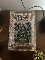
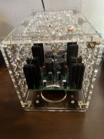
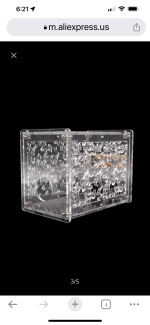
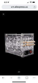
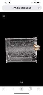
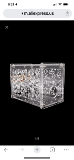
I just wanted to share the enclosure that I found for my ACA Mini. I found it on that Alie site. I had to add a couple stand offs to the sides to give the heat sinks a little more room. With all the holes in it the case doesn’t get hot. I though it was a neat way to protect it from little fingers.
I just wanted to share the enclosure that I found for my ACA Mini. I found it on that Alie site. I had to add a couple stand offs to the sides to give the heat sinks a little more room. With all the holes in it the case doesn’t get hot. I though it was a neat way to protect it from little fingers.
Attachments
Sure, here you go.
https://m.aliexpress.us/item/225183...crPKKU3&gatewayAdapt=glo2usa&_randl_shipto=US
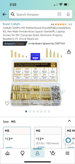
I added the shortest spacers brass from the set in the attached picture. They came from Amazon.
https://m.aliexpress.us/item/225183...crPKKU3&gatewayAdapt=glo2usa&_randl_shipto=US
I added the shortest spacers brass from the set in the attached picture. They came from Amazon.
Attachments
Just started building my ACA Mini...I noticed that the store sent me 1- 6.8K resistor and 2 - 22k resistors instead of 3- 6.8K resistors based on the BOM. Is that because of some modification of the BOM as product was optimized? If so am I OK to use the one 6.8K for R0 and the2- 22K for R4? Or should I go buy 2- 6.8K resistors for R4. Thanks in advance for any advice.
@RDamodaran , Check out previous post 1216 through 1218 here. The change is intentional to accommodate a more cost effective power supply.
A bit of quick help here please. I've started on my kits (essentials + sourced from BOM) and discovered I don't have the jumper bits. I can't for the life of me find the right words to search Digi . . . just the proper verbal name for the male blocks would be a great help. thanks!
- Home
- Amplifiers
- Pass Labs
- DIY ACA mini