Beautiful work, Olen! Your rev.0 prototype PCB in red, looks spectacular in that black chassis. Congratulations!I finished installing my almost clone of ACA Mini in a chassis. I bought a reproduction Dynaco ST-120 chassis from Dalaudio and it worked well.

This means 0.8 Ohm output impedance.
Where did you find this information or why do you know it?
"Oh, and I forgot - the damping factor is about 10."Look on page 11 of part 2.
Thanks, I have overseen this top line on the page 😁
OK, I give up. What is 'part 2' ? Thanks.Look on page 11 of part 2.
Look the attachments of post #1 of this thread. You will find two pdf's, part one and part two 😊OK, I give up. What is 'part 2' ? Thanks.
Thanks, I forgot about that. I downloaded the other version concatenated by ZenMod that had everything in one doc. BTW, 11 of 2 is the last page of both docs.Look the attachments of post #1 of this thread. You will find two pdf's, part one and part two 😊
FWIW here is a little something I've been woroking on so this design can be mounted in a conventional chassis with conventional heat sinks. It's the same size as the original ACA board. I'm trying to decide if I should move the MOSFETS to be even more like an ACA. I'm gonna order boards soon. If anyone has any layout commenst I'm all ears. I know I need to change the little electrolytic footprints to show polarity. It's been a while since I've done this.


Others may have differing opinions, but I liked the layout of the original ACA board because the MOSFETs were on the short side of the board, and as such could fit in a 2U chassis. In your current design, the MOSFETs will increase the width (height?) of the board when bent to attach to a heatsink, which might make it difficult to fit in a smaller enclosure.FWIW here is a little something I've been woroking on so this design can be mounted in a conventional chassis with conventional heat sinks. It's the same size as the original ACA board. I'm trying to decide if I should move the MOSFETS to be even more like an ACA. I'm gonna order boards soon. If anyone has any layout commenst I'm all ears. I know I need to change the little electrolytic footprints to show polarity. It's been a while since I've done this.
Thanks for your comment, your interest is appreciated. Perhaps the graphic is misleading. The MOSFETs sit no higher than on the original layout and both net physical height and board area are lower than with the ACA Mini layout ... and the length of the 'short' side of the board you reference is also less. At some point I'll put up actual dimensions but I'm still fine tuning the layout. BTW this board is for one channel so two can be installed on heatsinks on either side of a chassis.The two boards together take up less space than one ACA Mini board.Others may have differing opinions, but I liked the layout of the original ACA board because the MOSFETs were on the short side of the board, and as such could fit in a 2U chassis. In your current design, the MOSFETs will increase the width (height?) of the board when bent to attach to a heatsink, which might make it difficult to fit in a smaller enclosure.
Thank you for the kind words Mark and again for the boards.Beautiful work, Olen! Your rev.0 prototype PCB in red, looks spectacular in that black chassis. Congratulations!
For those interested I ended up buying 6 different lots of IRF520s and 9520s to get relatively well matched Vgs (~0.15V difference, both IR branded FETs), my first IRFs were from Jameco and one (I forgot which P or N) had a Vgs of around 2.0V and the other was nearly 4V! The parts from Jameco were two different brands. Later I ended up ordering 10 parts from each manufacturer that Mouser had in stock, each lot/group had a different mean Vgs but were consistent across the 10 like parts. It doesn't seem like there was much of a THD hit with (slightly) worse matching and not using Harris FETs. This evening I fired up my AP and measured the distortion and my plots looks fairly close to Papa's 😎 There was no issue biasing the amp and the heatsinks are pretty consistent temperatures (~50ºC).
(Jumper on) THD into 8Ω (1Vrms input ~5V across the output, 3.125W)
Frequency Repsonse (1V input, 8Ω load):
(Jumper On) THD (8Ω load) and gain (linearity)
Olen, I really like the nice work you have done. Great idea and nice execution. I may be statiing the obvious here but please bear with me. I see you did your tests with the jumper in which reduces total THD. It does that mainly by reducing the 2nd harmonic distortion which leaves 3d harmoninc the dominant audible distortion. So total THD is reduced but an odd harmonic becomes dominant. That is not necessarilly a good thing in my experience. This opens up the can of worms about whether or not conventional accepted measurements can indicate perceived sound quality. I personally prefer the sound with the jumper out. What is your feeling on that option and have you done measurements with the jumper out as well? Thanks and keep up the nice work!
Very nice work. If it was me, I would replace the 1 turn trim pot with one that has 12-20 turns, the bias would be easier to adjust. I’ve had that same concerns with the original ACA 10 years ago.Thanks for your comment, your interest is appreciated. Perhaps the graphic is misleading. The MOSFETs sit no higher than on the original layout and both net physical height and board area are lower than with the ACA Mini layout ... and the length of the 'short' side of the board you reference is also less. At some point I'll put up actual dimensions but I'm still fine tuning the layout. BTW this board is for one channel so two can be installed on heatsinks on either side of a chassis.The two boards together take up less space than one ACA Mini board.
Eric
That footprint already accepts 20 turn trimmer pots. Just buy the ones with the triangular / zigzag pin arrangement and scootch into the drill holes, then solder. TT Electronics model 67YR, Bourns model PV36Y, etc.
.
_
.
_
Attachments
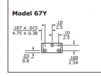
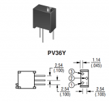
Cool! I'm gonna do that! BTW, would you happen to knbow if the pin arrangemnet is the same re CW vs CCW ?That footprint already accepts 20 turn trimmer pots. Just buy the ones with the triangular / zigzag pin arrangement and scootch into the drill holes, then solder. TT Electronics model 67YR, Bourns model PV36Y, etc.
.
_
The only way to know for sure is to download both datasheets: the 1-turn and the 20-turn. Then read carefully to see whether CW goes 1---->3 on both.
Hi Steve,Olen, I really like the nice work you have done. Great idea and nice execution. I may be statiing the obvious here but please bear with me. I see you did your tests with the jumper in which reduces total THD. It does that mainly by reducing the 2nd harmonic distortion which leaves 3d harmoninc the dominant audible distortion. So total THD is reduced but an odd harmonic becomes dominant. That is not necessarilly a good thing in my experience. This opens up the can of worms about whether or not conventional accepted measurements can indicate perceived sound quality. I personally prefer the sound with the jumper out. What is your feeling on that option and have you done measurements with the jumper out as well? Thanks and keep up the nice work!
I was just too lazy to pull the jumper and remeasure. I was going to give it a week to get used it
Hi Steve,Olen, I really like the nice work you have done. Great idea and nice execution. I may be statiing the obvious here but please bear with me. I see you did your tests with the jumper in which reduces total THD. It does that mainly by reducing the 2nd harmonic distortion which leaves 3d harmoninc the dominant audible distortion. So total THD is reduced but an odd harmonic becomes dominant. That is not necessarilly a good thing in my experience. This opens up the can of worms about whether or not conventional accepted measurements can indicate perceived sound quality. I personally prefer the sound with the jumper out. What is your feeling on that option and have you done measurements with the jumper out as well? Thanks and keep up the nice work!
In the ACA mini article Nelson measured THD with and without jumpers. The reason I ran the THD measurements was to check if I got similar results using IR FETs (check for P channel distortion) and check if the Vgs mismatch of ~0.15-0.2V made a difference. I didn’t have as good of a Vgs match as the Harris parts that Nelson so kindly provided for the official kits. The lower distortion with the jumpers in would make any measured difference more obvious.
I also prefer the sound of the jumpers out but I really have to listen for the difference (I’m not convinced I could tell the difference in a blind test). I have a theory that negative 2nd harmonic from the amplifier cancels when combined with the positive 2nd harmonic speaker distortion.
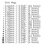
Hi all, I have a PCB questiion. I'm ready to send my gerbers out to get boards built so I can make an ACA Mini in a conventional chassis with conventional heat sinks. I noticed in the report that it will use 10 different drill sizes. Is this normal or something I need to address? I used the footprints provided by KiCad and also the Digi-Key parts lib as well. Thanks!!
| Count | Shape | X Size | Y Size | Plated | Via/Pad | Start Layer | Stop Layer |
|-------|-------|-------------|-------------|--------|---------|-------------|------------|
| 30 | Round | 31.50 mils | 31.50 mils | PTH | Pad | F.Cu | B.Cu |
| 10 | Round | 15.75 mils | 15.75 mils | PTH | Via | F.Cu | B.Cu |
| 8 | Round | 39.37 mils | 39.37 mils | PTH | Pad | F.Cu | B.Cu |
| 6 | Round | 55.12 mils | 55.12 mils | PTH | Pad | F.Cu | B.Cu |
| 6 | Round | 43.31 mils | 43.31 mils | PTH | Pad | F.Cu | B.Cu |
| 5 | Round | 66.93 mils | 66.93 mils | PTH | Pad | F.Cu | B.Cu |
| 4 | Round | 78.74 mils | 78.74 mils | PTH | Pad | F.Cu | B.Cu |
| 4 | Round | 30.00 mils | 30.00 mils | PTH | Pad | F.Cu | B.Cu |
| 3 | Round | 37.40 mils | 37.40 mils | PTH | Pad | F.Cu | B.Cu |
| 3 | Round | 137.80 mils | 137.80 mils | PTH | Pad | F.Cu | B.Cu | <- MOUNTING HOLES !
| 1 | Round | 137.80 mils | 137.80 mils | PTH | Pad | F.Cu | B.Cu |
I laid out my own PCB for an "Almost Clone" of the ACA Mini -- my rev.0 prototype is shown (here)
After a small board rev, member KevinHeem graciously supervised two Group Buys of these boards. The rev.1 boards that he shipped out, all over the world, had a total of 163 drilled holes. Here's a frequency table.
_
After a small board rev, member KevinHeem graciously supervised two Group Buys of these boards. The rev.1 boards that he shipped out, all over the world, had a total of 163 drilled holes. Here's a frequency table.
_
Attachments
- Home
- Amplifiers
- Pass Labs
- DIY ACA mini