I think Nelson tests TO220 mosfets at around 20mA using a 560 ohm resistor with a 15 V supply. You are testing at a lower current so less Vgs.
He beat me too it, these figures were from his paper years ago, nice to know it is 100mA now. Probably using something like a 120 ohm resistor.
He beat me too it, these figures were from his paper years ago, nice to know it is 100mA now. Probably using something like a 120 ohm resistor.
If you're going to be testing LOTS of MOSFETs, it might be a good idea for you to design and build (and verify proper operation of) a temperature stable, 100 mA constant current source. Solder it together on a little scrap of stripboard or vero board or experimenters perfboard and put in your toolbox. Voila, every MOSFET you subsequently test with that CCS, is guaranteed to be measured at the exact same current. Where "exact" means "close enough to placate hobbyist purists".
You could consider adding a 2-pin header + jumper, to enable a second and different constant current. Perhaps 10mA?
You could consider adding a 2-pin header + jumper, to enable a second and different constant current. Perhaps 10mA?
If you are trying to be that accurate then also regulate ambient temperature and have a consistent length of test duration.
Me, I only try for 0.1V accuracy.
Me, I only try for 0.1V accuracy.
Just matched some Toshiba TO220 mosfets at 100mA (Reg 15Vdc supply with R = 120 ohms), found the Vgs stabilised after 15 seconds or so, but tested all for exactly 1 minute each at the same temp (25C). Got 2 matched pairs for Vgs at 0.010V max difference. Will try these in the mini ACA.
I just measured out a small pile of the onsemi p-channel device FQP3P20 at 12V and ~70mA, and they gave a Vgs from 4.09 to 4.34. The only n-channel device I had that was close was a single example of the IRF530N, which was right at 4.34. Alas I only have one. The IRF510 and IRF610's I had were lower by half to one volt, the IRF4905 which is a hilariously low Rds(on) had a Vgs of 0.65. The search continues.
Yes that's it.Maybe because you are measuring at a different current to what his test jig allows.
I retested some IRF520 which had measured 3.5 Vgs at 5mA. They measure around 4.0Vgs at 100mA.
That is exactly what I have found with my testing, the lower the current - the lower is the Vgs figure. So that raises a question as to what current for any given fet should one be testing to get the ideal Vgs matched sets? For example with the ACA MINI amp the output fets are biased to 400mA according to Nelson's instructions, but he matches these devices at a current of 100mA. I wonder if there is a rule of thumb that Nelson applies when matching, depending on the device and ultimate current it will be used at in the circuit?
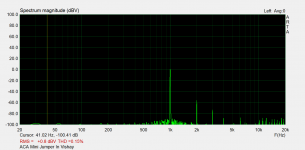
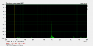
The IRF 9520 and 520 manufactured by Vishay came in from Mouser today. They measured very consistently within their type, around 3.9Vgs for the N channel and about 3.6Vgs for the P channels (testing at 100mA). So no really close matches here. I only had 10 of each type.
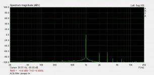
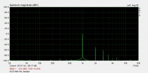
I installed the Vishay parts in the ACA Mini and got these measurements. Slides 3 and 4 are reposts of the (maybe) Harris parts for comparison.
I installed the Vishay parts in the ACA Mini and got these measurements. Slides 3 and 4 are reposts of the (maybe) Harris parts for comparison.
Attachments
Last edited:
Ok, gave the amp a try in my big system. It is definitely a Pass amp: totally quiet, lots o detail without being “hifi”
Ie it’s relaxed but music is all there!
Ie it’s relaxed but music is all there!
Ok, I'm going to build one of these with the onsemi MOSFETs in place of the Harris parts, because that's what I can source and Vgs match. The main difference I can see is in the higher Rds(on) and lower gate capacitance of the onsemi parts:
HARRIS IRF9520
Rds(on) = 0R6
Gfs = 0.9-2
Crss = 50pF
FQP3P20
Rds(on) = 2R06-2R7
Gfs = 1.23
Crss = 7.5pF
HARRIS IRF520
Rds(on) = 0R27
Gfs = 2.7-4.1
Crss = 25pF
FQP3N30
Rds(on) = 2R2
Gfs = 1.75
Crss = 6pF
I am thinking to drop the values of the source degeneration resistors R8 and R9. What would be easy/convenient for me is a drop from 0R75 to 0R47, or all the way down to 0R1. Thoughts? Does the lower gate capacitance necessitate any other changes?

Ranshdow - I'd not worry about it and just leave the values as designed, the Fairchilds will work wonderfully.
Something I learned from experience and probably obvious…if you’re going to experiment with output transistor in this amp DON’T solder the heat sinks in place until you settle on which transistors you want to use permanently.
Last edited:
6L6, I'm thinking now that the gain difference which drives the 2nd harmonic character of the ACA mini might be much less pronounced with the Fairchilds. Of course the answer is to build and test, but rn distortion analysis is beyond my ken.Ranshdow - I'd not worry about it and just leave the values as designed, the Fairchilds will work wonderfully.
Since today, I am testing my "Almost Clone of ACA Mini".
I am running it with VB 0.3V and VO 11.5V. The heathsinks are at the hottest spot between 55 and 57 degree celsius.
Is this to hot?

I am running it with VB 0.3V and VO 11.5V. The heathsinks are at the hottest spot between 55 and 57 degree celsius.
Is this to hot?
if he live forever at 21° ...... standard Nelson guide is +25 that's at 30°summer perfect 55°Standard repost of Nelson Pass's guideline: (LINK)
I applied a very thin film of a thermal greaseStandard repost of Nelson Pass's guideline: (LINK)
If you don't have a Bergquist Sil-Pad between the TO-220 and the heatsink, and if you also don't have a smear of Aavid Thermacote heatsink "goop" between the TO-220 and the heatsink, add one or the other. It's hard to tell from the photograph.
- Home
- Amplifiers
- Pass Labs
- DIY ACA mini