This reminds me of a question I have - if using a line level crossover, do people us a series cap to protect the tweeter too, or is the tweeter safe?
I was wondering if it would be an upgrade to replace the 15000uF output capacitor with a 10~20 uF film capacitor since I will only use the amp from 3kHz on up, or does this only screw things up?
What sort of impedance is the compression driver?
@Stanislav is correct saying that the input cap should really define the response to a large extent.
This assumes 6 ohm impedance and has just 2200pF as the input cap, 47uF as the feedback return and 20uF output coupling cap. For 6 ohms 20uF looks to small to me as it is still playing a big part in the response here.
Vo is before the 20uF cap.

This reminds me of a question I have - if using a line level crossover, do people us a series cap to protect the tweeter too, or is the tweeter safe?
If you just want a 1st order PLLXO, the series cap/parallel resistor can be replaced by suitable choice of input cap. The input of the amp becomes th PLLXO. ie instead of a C-R in series with the C-R in the input, you change the input cap to get the same response.
I do this wi6h my ACAs.
dave
I am new to DIY amps, and just purchased the mini. Looking forward to learning about this side of the DIY audio ecosystem. One question:
I notice there is no transformer, and instead it uses a SMPS. Does increasing the voltage/amperage of the power supply increase the output...or does it need to stay with the included power supply?
I notice there is no transformer, and instead it uses a SMPS. Does increasing the voltage/amperage of the power supply increase the output...or does it need to stay with the included power supply?
The included supply is best option all round.
A higher voltage can enable higher output voltage into the load (ultimately the supply voltage determines the output of any normal amp like this) but there are big downsides to doing that, mainly excess heat in the output stage of the amp. You would need to go a lot higher in voltage to get a subjectively 'louder' amp and the heatsinks would need to be several times larger than they are now. The bias current would be increased and the current capability of the power supply would need to be much greater.
So keep it all as is 🙂
On top on what Mooly already explained, considering this time more the sound than the raw power delivery...
Whereas SMPS are quite criticised - and I wouldn't want one for a Class AB amp for example- , I found once filtered properly they could do a good job with Class A amps (nearly constant draw... plus regulated is often better for PSR) and Class D amps (HF pulse, impedance?).
Here we are in Class A so quite acceptable IMHO - and Papa wouldn't have gone for it if it wasn't ;-).
Regarding the SMPS specs, I wouldn't increase the voltage especialy if you are new to DIY: some critical parts have a limit at 25V here and would need replacement, not to mention what Mooly already said. As of current, I found increasing the SMPS capability to 5A was better sounding, and that despite filtering and of course well noting that we don't even need 2A...
Last but not least, you could at a minimum consider the tweak with the coil to get the best of the SMPS (whatever unit you have), and -if you fancy it- the caps tweaks (one is around the PS filtering caps). All these can be done with ANY SMPS...
I hope this helps
Claude
@ross51681 If you're looking for an ACA Mini with more voltage / amperage / power, may I suggest the ACA MinMax?
Here's the thread and the store's project page.
Here's the thread and the store's project page.
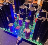
I finished up my seventh ACA Mini last night (I like to give as gifts to family and friends), but ran into an "issue" around 2AM so I didn't get music playing until today. Now it's all dialed in with Vb = 0.35VDC and Vo=11.5VDC on both sides. I used 25 turn pots on this one, and I do like the fidelity it provides. However, they did help exacerbate the issue I ran into, which will be covered shortly (sneak peak...it was user error).
First, let me just say, every time I hook up an ACA Mini and play some tunes I am just absolutely amazed. On this go, I am running it with some old ADS L470's, and they are just making sweet tunes. Bass is actually pretty good on these speakers. As those who have heard this amp know, the mids and highs are unbelievably good. It's gotta be the simplicity and size that makes it so mind blowing that it can sound this good. I'll just end now with it's still one of the best sounding amps I've heard. (Thank you Papa!)
I'm currently using with @ClaudeG's suggested Murata coil in one of my fancy 3D printed boxes. I haven't done a fair AB comparison with/without the coil, so I can't comment on if there's a noticeable difference in sound yet.
Ok, time to share in my re-learning...The "issue" I ran into which sent me on a near 3 hour wild goose chase until I gave up, looked at the thread, and quickly slapped my hand to forehead that I was so dumb. First, in attempting to defend myself a bit, it was 2AM when I finished populating the amp, so my brain was operating at maybe 50% by then and I was partially distracted by a "Back to the Future" trilogy marathon on tv. My issue was I was using Ground to Vb as my "bias" check. I kept getting 24VDC and I was so confused. I spent the next 2.5 hours troubleshooting (I won't describe the insane things I tried and did in hunting for the "problem") before giving up, going to bed, and reading the thread where someone else had the same issue.
You'd think after building 7 of these myself I'd know that Vb is measured at the two test points next to the "Vb" printed on the board. I'm a dodo....I was a really BIG dodo last night.
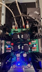
So, to help that one other person who might just make the same mistake as me, here's one more picture showing where to measure Vb and Vo.
Bias is measured by the two test points next to the "VB" label (the GND test point is not part of this) and should be 0.30 to 0.35 VDC per Nelson's article guidance.

Measuring the offset, V0 target of 11.5 VDC (between 11.4 to 11.6 is good per article) uses the test points marked GND and Vo.

First, let me just say, every time I hook up an ACA Mini and play some tunes I am just absolutely amazed. On this go, I am running it with some old ADS L470's, and they are just making sweet tunes. Bass is actually pretty good on these speakers. As those who have heard this amp know, the mids and highs are unbelievably good. It's gotta be the simplicity and size that makes it so mind blowing that it can sound this good. I'll just end now with it's still one of the best sounding amps I've heard. (Thank you Papa!)
I'm currently using with @ClaudeG's suggested Murata coil in one of my fancy 3D printed boxes. I haven't done a fair AB comparison with/without the coil, so I can't comment on if there's a noticeable difference in sound yet.
Ok, time to share in my re-learning...The "issue" I ran into which sent me on a near 3 hour wild goose chase until I gave up, looked at the thread, and quickly slapped my hand to forehead that I was so dumb. First, in attempting to defend myself a bit, it was 2AM when I finished populating the amp, so my brain was operating at maybe 50% by then and I was partially distracted by a "Back to the Future" trilogy marathon on tv. My issue was I was using Ground to Vb as my "bias" check. I kept getting 24VDC and I was so confused. I spent the next 2.5 hours troubleshooting (I won't describe the insane things I tried and did in hunting for the "problem") before giving up, going to bed, and reading the thread where someone else had the same issue.
You'd think after building 7 of these myself I'd know that Vb is measured at the two test points next to the "Vb" printed on the board. I'm a dodo....I was a really BIG dodo last night.
So, to help that one other person who might just make the same mistake as me, here's one more picture showing where to measure Vb and Vo.
Bias is measured by the two test points next to the "VB" label (the GND test point is not part of this) and should be 0.30 to 0.35 VDC per Nelson's article guidance.
Measuring the offset, V0 target of 11.5 VDC (between 11.4 to 11.6 is good per article) uses the test points marked GND and Vo.
Attachments

Last edited:
Fist off... Whaou, 7 MINIs!!!
7 Minis....
7...
!!!
You clearly beat me, and eventhough my "demo Mini" hasn't been yet really on a big tour at friend's, I doubt I can beat that one day LOL!
But I agree, that little gem deserves to be shared and is the ideal introduction to Papa's DIY. Easy build, low cost, VFM is absolutely great and the look is so cute (and it can be tailored). Sound can even be tweaked... and 2 of them (double Mono configuration) seem to be even much better for whatever reason ...what is it not to like?
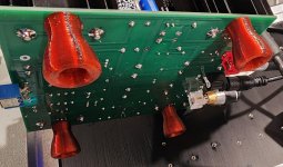
Then... THESE SEXY FEET!!! What a beauty! I like also the underslung connections, very nice! Well done again, Dan!
Now to the build. 2AM... Nah, first rule: don't work seriously at 2AM! Oh, I love working at night, and I believe easily you made such a mistake... if you remember my first Mini at 2AM I soldered one of the transistors backwards (lucky me I noticed it while soldering the 3rd one, something just felt odd LOL). So, Dan, given we live thousands of miles apart, it MUST be clearly the 2AM and defo not us! Next time, stop at 1.59AM... and start again at 2.01AM, but make sure you have an accurate clock... that 2AM is very clever 🙂))
And now- perhaps a useful hint - for other builders? That VB measurement can be tricky: some might be afraid to have clumsy fingers, space is tight etc..
In fact, if I remember well, VB is "simply" taken across R8. R8 is one of the big resistors, hence I mount it say "nearly 1cm or so" above the board so this 2W resistor can get some air around of it. Also, R8 stands quite alone, is hence accessible... and has big legs. I never used the tiny and close together VB points: I simply used crocodiles or even touch probes directly at the legs of R8, far easier and probably safer late at night LOL.
I found this easier "for me", but then of course, that's just me...
Have a nice day and well done again!
Claude
7 Minis....
7...
!!!
You clearly beat me, and eventhough my "demo Mini" hasn't been yet really on a big tour at friend's, I doubt I can beat that one day LOL!
But I agree, that little gem deserves to be shared and is the ideal introduction to Papa's DIY. Easy build, low cost, VFM is absolutely great and the look is so cute (and it can be tailored). Sound can even be tweaked... and 2 of them (double Mono configuration) seem to be even much better for whatever reason ...what is it not to like?
Then... THESE SEXY FEET!!! What a beauty! I like also the underslung connections, very nice! Well done again, Dan!
Now to the build. 2AM... Nah, first rule: don't work seriously at 2AM! Oh, I love working at night, and I believe easily you made such a mistake... if you remember my first Mini at 2AM I soldered one of the transistors backwards (lucky me I noticed it while soldering the 3rd one, something just felt odd LOL). So, Dan, given we live thousands of miles apart, it MUST be clearly the 2AM and defo not us! Next time, stop at 1.59AM... and start again at 2.01AM, but make sure you have an accurate clock... that 2AM is very clever 🙂))
And now- perhaps a useful hint - for other builders? That VB measurement can be tricky: some might be afraid to have clumsy fingers, space is tight etc..
In fact, if I remember well, VB is "simply" taken across R8. R8 is one of the big resistors, hence I mount it say "nearly 1cm or so" above the board so this 2W resistor can get some air around of it. Also, R8 stands quite alone, is hence accessible... and has big legs. I never used the tiny and close together VB points: I simply used crocodiles or even touch probes directly at the legs of R8, far easier and probably safer late at night LOL.
I found this easier "for me", but then of course, that's just me...
Have a nice day and well done again!
Claude
Kudos to birdbox on completing 7 ACA Minis.
Claudes's suggestion for clipping onto the R8 leads is great for the initial phases of setup, esp. when using 2 meters simultaneously. However, for quick spot checks (a good idea during seasonal T changes), I find pressing the probe tips into the solder pads/vias at the Vb points to be super convenient and quick; brilliant minimalist design, IMO.
Below is the ACA Mini schematic marked with the Vb points and the Vo point. I had posted this at some point in the early part of this now-long thread, but repeat it here in case some find if helpful (although it's utility at 2AM, like most things, is doubtful).
vias... I had a random thought.
Are you supposed to fill via holes with solder or solder in fine wire or... not?
is that a bad idea.. or not?
Are you supposed to fill via holes with solder or solder in fine wire or... not?
is that a bad idea.. or not?
Just got my ACA Mini last night and will be putting it together this weekend. 🙂
I plan to make a wooden case and mount rca, speaker, and power jacks on the back, and a switch on the front. The RCA jacks and binding posts I know how to handle. A couple questions regarding power supply and switches:
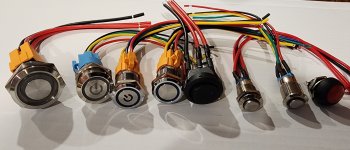
1. On the front I would prefer to use a toggle or led push button power switch...are there some that you guys can recommend? Im a little confused also at what voltage/amperage i should get...should it match the power supply (24V)?
2. To install the power jack in the back of the case...I haven't had time to inspect all the included parts. Will the included female power jack be able to be mounted in the case or do I need to look for something else online?
Thanks so much!
I plan to make a wooden case and mount rca, speaker, and power jacks on the back, and a switch on the front. The RCA jacks and binding posts I know how to handle. A couple questions regarding power supply and switches:
1. On the front I would prefer to use a toggle or led push button power switch...are there some that you guys can recommend? Im a little confused also at what voltage/amperage i should get...should it match the power supply (24V)?
2. To install the power jack in the back of the case...I haven't had time to inspect all the included parts. Will the included female power jack be able to be mounted in the case or do I need to look for something else online?
Thanks so much!
I would purchase a 5x2.5mm female barrel connector meant to be mounted to chassis, like this. There are also ones that come with pre-soldered leads. Just make sure it's capable of at least 2.5A to be as capable as the one included with the kit.2. To install the power jack in the back of the case
The switch that came with the kit should mount to chassis if you'd like to use that and avoid buying another switch. I've had good results with push button switches off the big bezos bookstore. Here's one I used with my MinMax.On the front I would prefer to use a toggle or led push button power switch
There are lots of options from the largest rainforest on the planet.
Attachments
Last edited:
+1 on Birdbox!
An additional note, just in case of...
The original power switch (as in the kit) isn't exactly a conventional power switch: it doesn't switch off the entire PS of the amp, like usual commercial switches do for example.
Having a plug with an ON/OFF switch, on which you plug the SMPS main's plug, could be an easy way to switch everything off in one go (SMPS and hence amp completely off)...
Claude
- Home
- Amplifiers
- Pass Labs
- DIY ACA mini